MPCNC part 4
Squaring the frame
I 3D printed the first 10 layers of the MPCNC foot object to use as a template for drawing the screw holes in the table. I used a laser range finder to measure distance and square the frame. As the table was cut to size accurately, I could use the edge as a reference.
Connecting GT2 belts
The GT2 6mm rubber belt was relatively easy to install. Don’t over tighten just yet; you can always do this later. I can strongly recommend the following GT2 6mm cable tie timing belt clips. Simply loop the GT2 belt back onto itself with interlocking teeth and secure with a cable tie. Connect the loop of the GT2 belt to the MPCNC corner post with a cable tie.
https://www.thingiverse.com/thing:746423
GT2_Belt_Clip.zip (STL file)
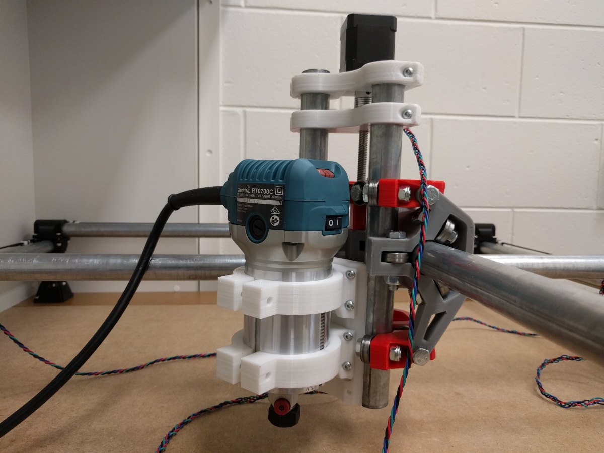
Makita RT0700CX 710W router spindle
This router is easy to mount, powerful and has variable speed control (no computer controlled variable frequency drive unfortunately) and is limited to 1/4inch shank milling bits (1/4inch to 1/8inch collet adapters are available on the internet).
https://www.thingiverse.com/thing:2235410
MPCNC_mounting_bracket_for_Makita_RT0700CX_router.zip (ZIP file)
A suitable dust boot can be found here:
http://www.thingiverse.com/thing:2235428
There is an optimized Makita router bracket available that sits closest to the Z axis and has through holes to access the bolts for tightening:
https://www.thingiverse.com/thing:3500550
Optimized_Makita_RT0701C_Mount_for_MPCNC.zip
I will keep using the existing two brackets as they sit fairly close to the Z axis already. They weigh a bit less and take not as long to 3D print if one of them fails. Bolts are somewhat difficult to access but it is manageable.
ER11 collet set
The Makita RT0700CX collet only supports a single size cutting / drill bits shaft: 6.35mm (1/4”) bits.
You can purchase a 1/4″ to 1/8″ reducer to clamp 3.175mm (1/8″) bits:

In hindsight, these reduces are dirt cheap and turned out to be all that I needed to get started. Just order 10 of them and leave them on your small drills / milling bits.
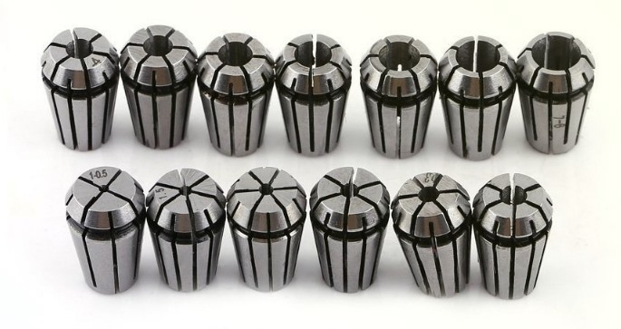
If you want more flexibility you can switch to an ER11 collet set. WARNING: this will increase stick out. This allows for cutting / drill bits with a shaft diameter of 1 / 1.5 / 2 / 2.5 / 3 / 3.5 / 4 / 4.5 / 5 / 5.5 / 6 / 6.5 / 7mm (13 pieces set):
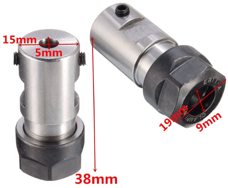
You can purchase a simple ER11 collet adapter coupler with ER11A style nut and 5mm shaft hole to connect to the Makita RT0700CX using a 5mm diameter piece of shaft from a drill bit or similar:
If you want more rigidity you can purchase a “C6 ER11A 60L” adapter with a 60mm long 6mm diameter shaft firmly connected to the ER11 collet:
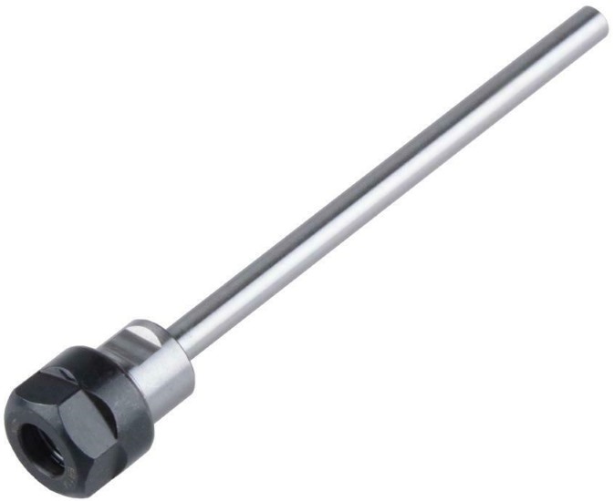
You can simply cut the shaft to the desired length and insert the adapter into the Makita RT0700CX 6.35mm (1/4inch) collet.
WARNING: unnecessary unpractical amount of stick out!
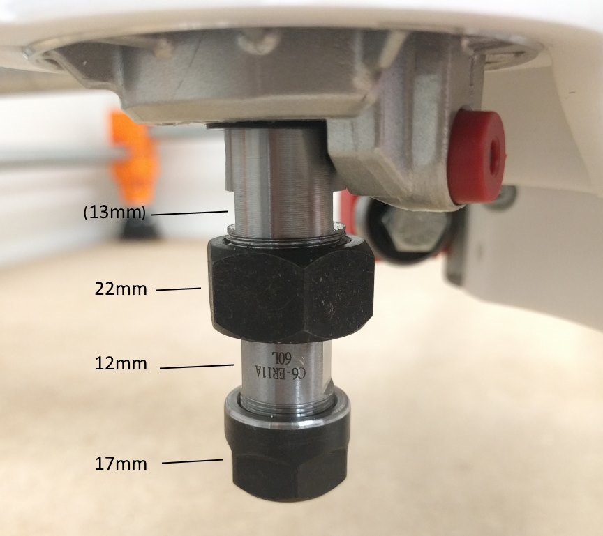
Bring out your spanners…
I have since abandoned all this and just used 1/4″ shank bits/drills and the 1/4″ to 1/8″ reducer. Works okay’ish.
Corner posts “Totem”
I had a lot of problems tightening the metric nyloc nuts on the 25.4mm (1″) corner posts. I had to wedge a screwdriver between the nut and the corner bracket to stop the nut from spinning when tightening. This caused the plastic to crack. There are ‘cups’ you can 3D print to fit around metric nuts for a tighter fit. The two halves of the bracket do not sit flush, which is somewhat unsightly.
So I started looking at the “totem” corner post brackets mod:
 Totem_mpcnc_corner_rethink_25.4mm_and_23.45mm.zip
Here are my 3D printed parts:

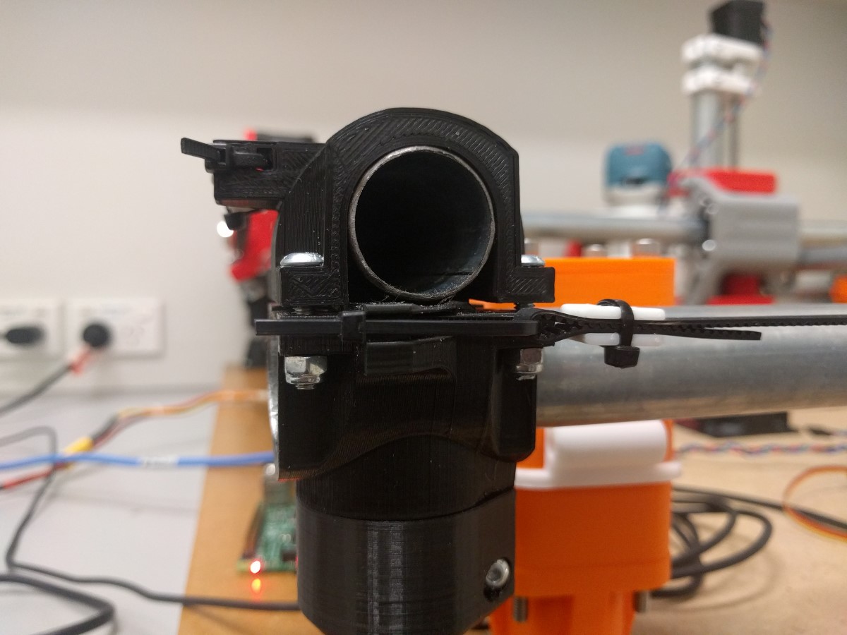
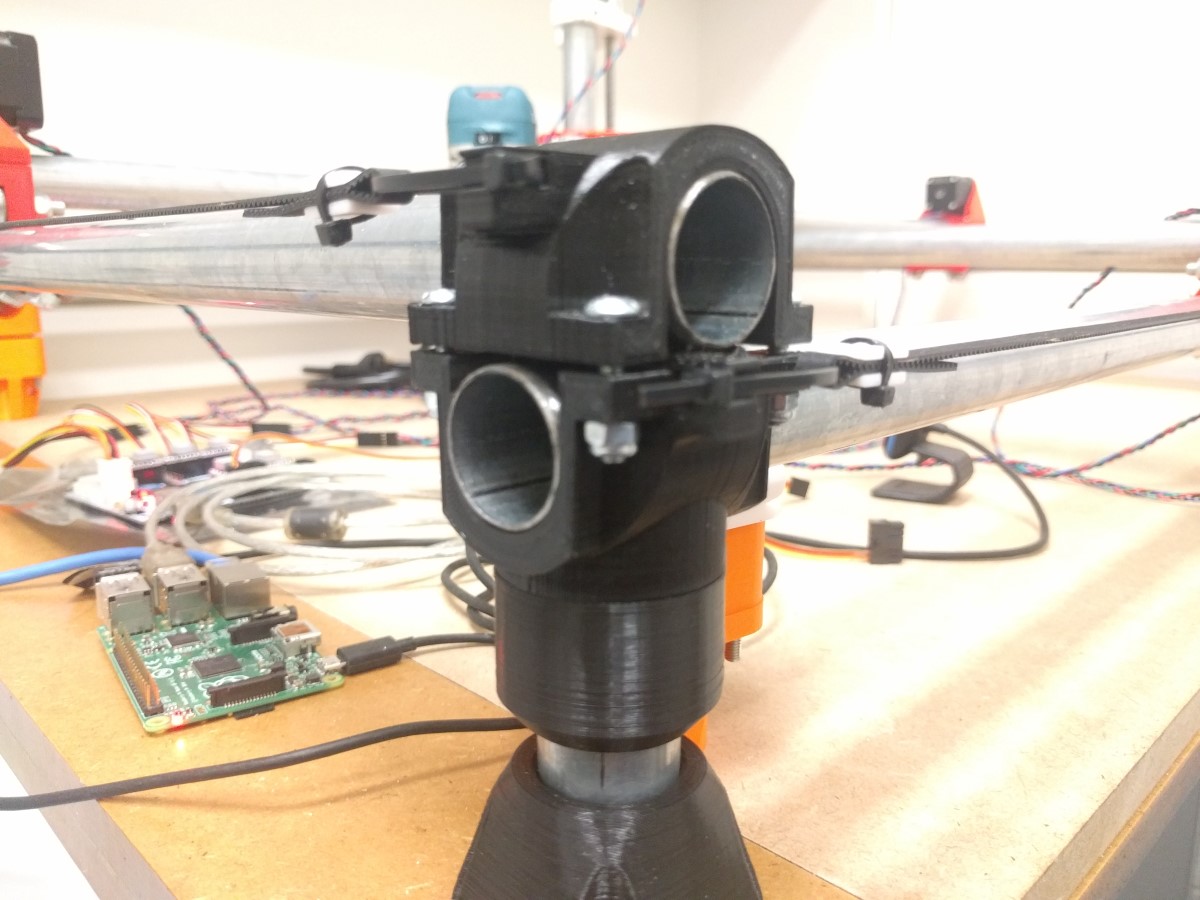
The ‘totem’ consists of the following elements:
switch_top_rail
top_and_bottom_clamp (#2)
belt_clamp + bottom_rail_switch
middle_joiner
belt_clamp
top_and_bottom_clamp (#1)
base_clamp
foot
You will need 16x M5x100 hex bolts and nuts for the totem assembly. I used 304 stainless steel.
You can print a spacer for corner posts that don’t need end switches, but I found it easier to make all corner posts identical. This also gives you a few spare parts if you ever need them without having to 3D print.
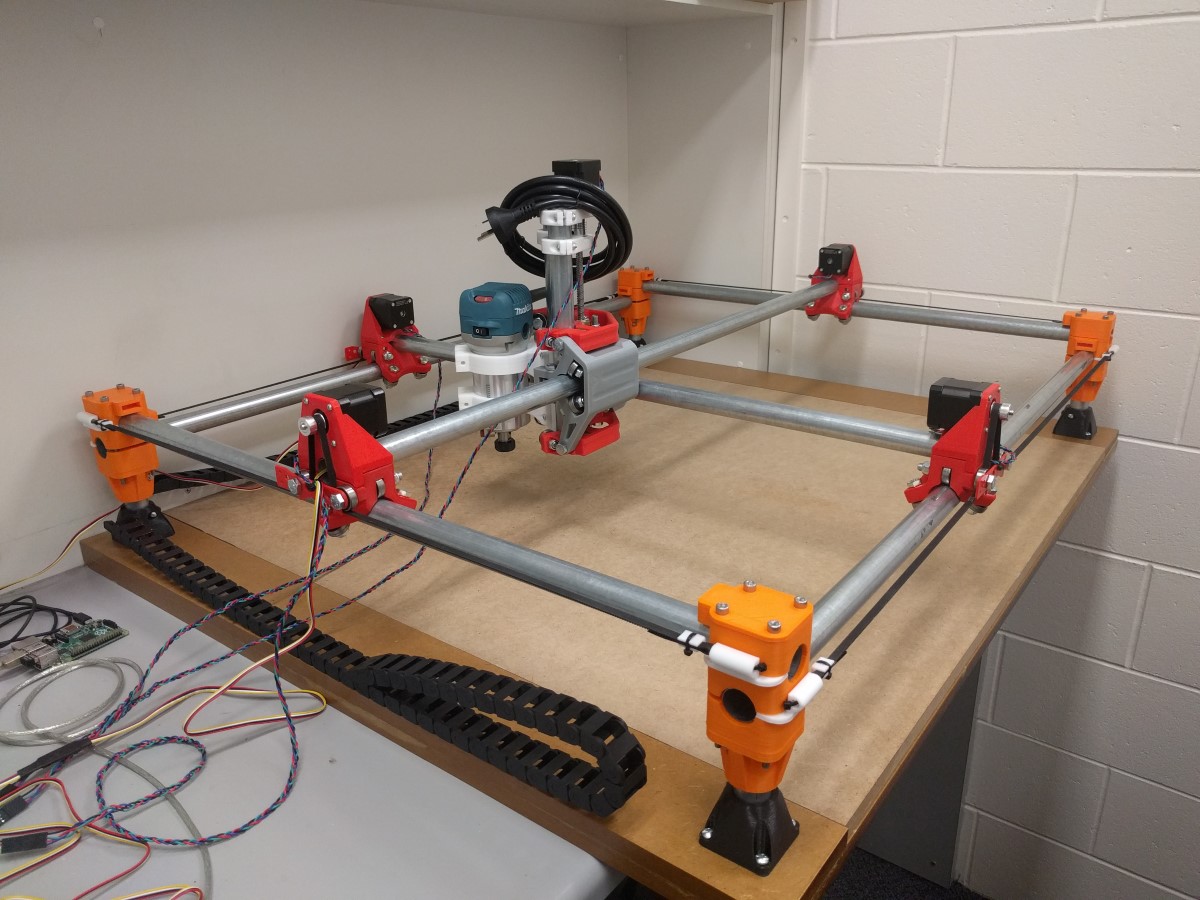
Note how the cable ties run through the hollow white corner guide as you would expect but then return wedged in between the orange and white plastic parts. This is to ensure the GT2 belt runs paralllel with the round tube. Initially the cable tie return would sit on the outside of the hollow white corner guide, but this resulted in the GT2 belt not sitting parallel to the round tube.
Electronics
The stepper motors come with Dupont 2.54mm (0.1 inch) pitch header connectors. You can gently lift the small black retaining pin of each of the four connectors with a precision knife and slide out the metal pins. You can braid the wires for a tidy finish. As these wires are connected to stepper motor coils and not sensitive input signal wires (end stop switches), signal interference is not a concern.
Test stepper motors
I used the following basic Arduino stepper motor driver example to test the X, Y and Z axis.
As the easystepper board can only supply 12V 750mA max, I had difficulties moving the X, Y and Z axis. The symptoms were the stepper motors making noise and missing steps. I had to loosen the screws that held the leadscrew nuts in place. This allowed the leadscrew nut to orient itself freely to the leadscrew. After applying some lithium grease I and supporting the Z axis when moving up, after a few attempts the Z axis moved up and down properly. I can now start looking at the proper electronics.
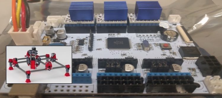
Choice of logic board
As I own a Geeetech A10 printer to 3D print parts, I thought I’d use the same logic board and power supply. The Geeetech A10 printers use an open sourced design GT2560 v3 logic board and 24Vdc power supply. There are some pros and cons to this decision:
Pros
- 24Vdc board
- Supports A4988 / DRV8825 / TMC2208 stepper drivers.
- Open source design: GT2560_V3.0_Schematic.pdf
- Arduino MEGA 2560 + Bootloader + Marlin = easy to flash firmware.
Cons
- LCD / SDCARD connector is a non-standard 40 pin ribbon cable. Popular “LCD2004” type LCD screens available do not include an SD card slot and use different connectors. As I will be using CNCjs on a Raspberry Pi connected over USB not having an LCD screen or SD Card is acceptable.
- Only supports 3 limit switches (X, Y, Z) using JST XH, 2.5mm, 2-pin connectors. MPCNC ‘dual endstops’ mod requires five endstop inputs X1, X2, Y1, Y2, Z (probing).
- GT2560 v3 boards are not as popular nor as readily available as RAMPS v1.4 or MKS Gen L v1.0 boards.
- X,Y,Z stepper motors use JST XH 2.5mm pitch 4 pin connectors to connect to the logic board.
- (E0),E1,E2 extruder stepper motor connectors use Molex Micro Fit 12 pin connectors (2×6 dual row).
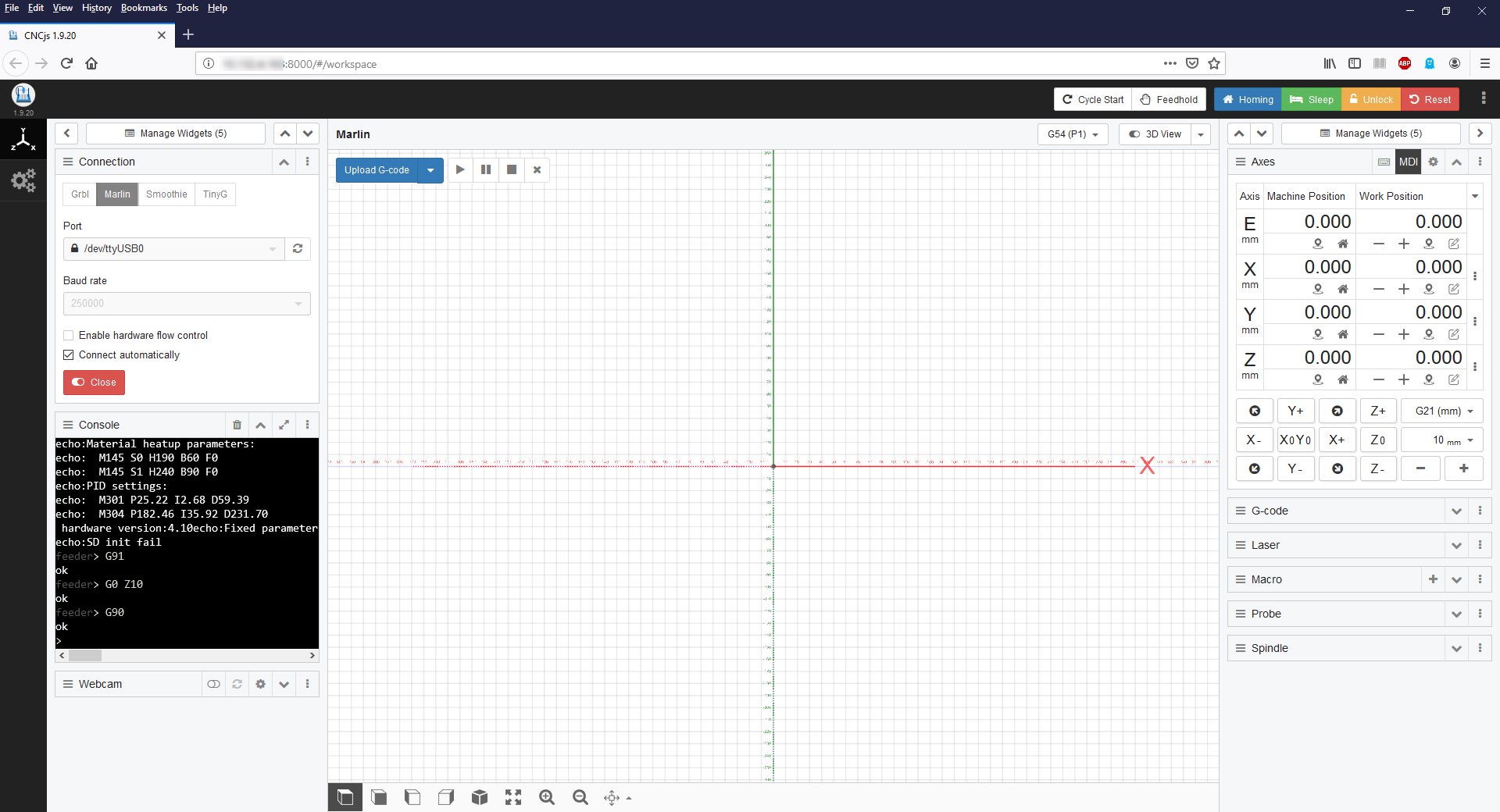
Raspberry Pi
I used a Raspberry Pi 3B+ v1.2 2014 and installed Raspbian Stretch Lite and CNC.js:
https://cnc.js.org/docs/rpi-setup-guide/
I was able to connect to the web interface on port 8000 over a wired network connection.
I plugged the Raspberry Pi into the GT2560 v3 logic board of my Geeetech A10 3D printer and selected Marlin, USB port and 250000 Baud rate. It was very easy to move the X, Y and Z axis of the 3D printer. I had one problem where the digital coordinate readout did not show the correct values, but this was resolved by using a shorter USB cable with a ferrite choke.
Webcam
You can connect a webcam to the Raspberry Pi and view the video stream in CNC.js
If you receive the message “failed to start” you may want to edit the script and temporarily change the following line:
INPUT_OPTIONS=”-r ${RESOLUTION} -d ${VIDEO_DEV} -q ${QUALITY} -pl 60hz –every_frame 2″
to this:
INPUT_OPTIONS=”-r 640×480 -d /dev/video0″
In my case the “-q ${QUALITY}” option was not supported on Raspbian Stretch.
In the end I used the original line of code and simply omitted the “-q ${QUALITY}” option.
You can test the webcam feed by using the following link:
http://<ip-address>:8081
In CNC.js you can connect to the video stream using the following link in the settings of the Webcam widget:
http://<ip-address>:8081?action=stream
I was now ready to connect the Raspberry Pi to my MPCNC GT2560 v3 logic board. I just had to install the stepper motor driver boards first.
Stepsticks
Here is a list of common stepper motor driver boards also known as ‘stepsticks’.
Jumpers MS1, MS2 (and MS3) control the microstepping.
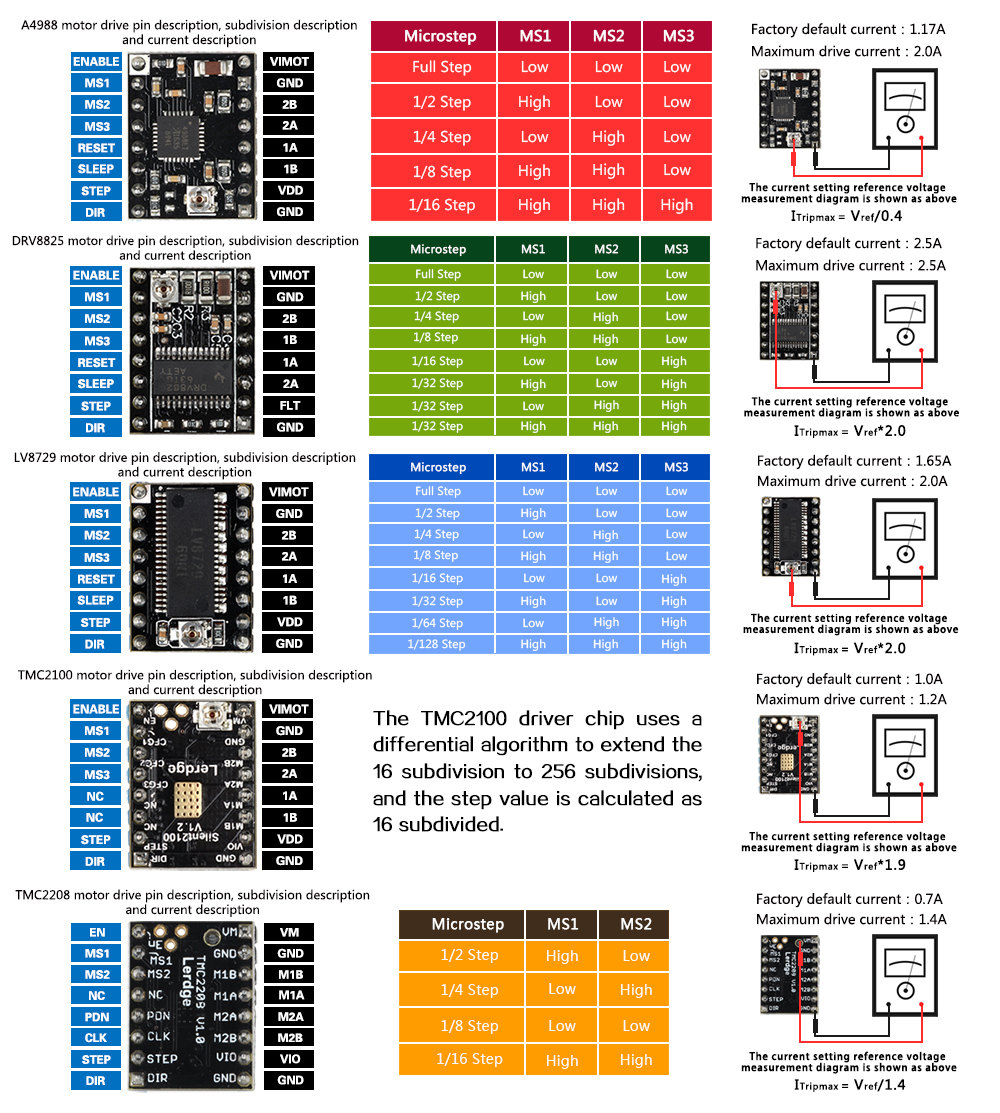
My NEMA 17 stepper motor coils can handle 2A to 2.5A of current. The stepsticks listed in the table can deliver 1.4A to 2.5A of current. Vref values need to be set as follows:
A4988: I = Vref / 0.4 = Vref * 2.5 = 2.0A Vref = 0.8V
DRV8825: I = Vref * 2.0 = 2.0A Vref = 1V
TMC2208: I = Vref / 1.4 = 1.4A Vref = 1V
Place one multimeter probe on the potentiometer rotating contact and the second multimeter probe on a GND pin of the stepstick module measure the voltage. The logic board needs to be powered up. The stepper motors are best left disconnected. Do not connect/disconnect stepper motors while the logic board is powered up.
It is recommended to install a small cooling fan to cool the heat sink. A little bit of airflow goes a long way. The GT2560 v3.0 logic board uses a JST PH, 2mm, 3-pin connector for the fan.
I will use 5x DRV8825 stepsticks in my MPCNC machine:
Replacing my 3D printer’s A4988 stepsticks with TMC2208 stepsticks
Here is an instruction video how to -for example- replace Allegro A4988 stepper drivers with TMC2208 trinamic stepper driver boards. Please skip if not of interest.
https://www.youtube.com/watch?v=TubpTMFkbVs
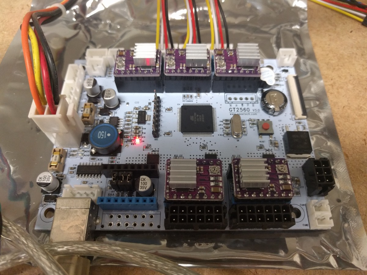
Note the correct orientation of the heat sink:
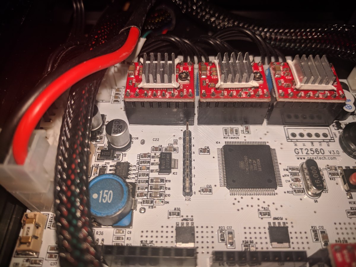
GT2560 v3.0 with A4988 stepper drivers for X, Y and Z axis.
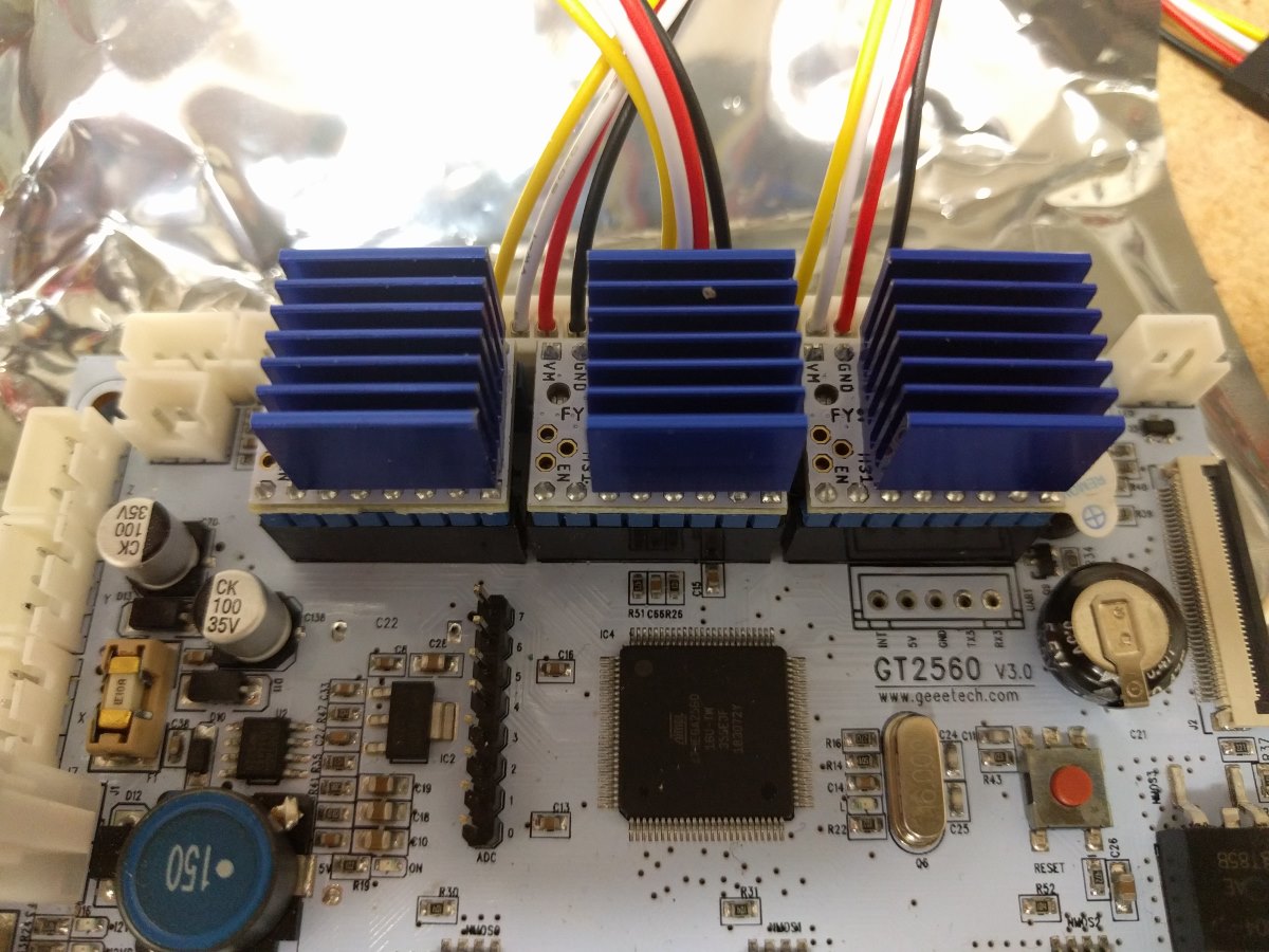
Note the orientation of the TMC2208 stepper driver boards. Do not connect blue pin connector to blue pin connector and black pin connector to black pin connector. These stepper drivers are plugged in with the blue/black colors NOT matching on a GT2560 v3.0 logic board.
GT2560 v3.0 with TMC2208 trinamic stepper drivers for X, Y and Z axis.
The A4988 and TMC2208 stepsticks both support 1/16 microstepping. The TMC2208 is a direct replacement for the A4988. The only surprise is that all motor axis were inverted. As you can’t flip the stepper motor connector on a 3D printer I had to invert the stepper motor direction in Marlin firmware and upload to the logic board to correct this behavior. 3D printer runs extremely quiet with little to no difference to print quality as expected.