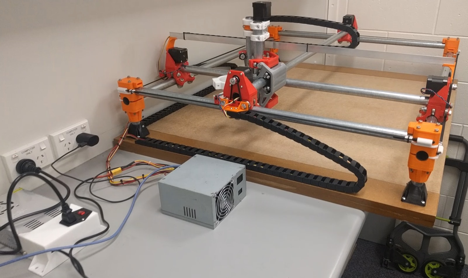
MPCNC part 5
GCODE maiden flight
Some important Gcode instructions:
G20 = everything is in inches
G21 = everything is in mm
G90 = everything is in absolute coordinates (go to coordinate position)
G0 X30 = move to absolute X coordinate position ’30’ on the X axis.
G91 = relative coordinates (move relative from current position)
G0 Z30 = move 30mm vertically up relative to current position (= positive Z axis value)
G0 F600 = set feedrate to 600mm/min for all subsequent move commands = 10mm/sec = 1cm/sec = slow
G0 F6000 = set feedrate to 10cm/sec = fast
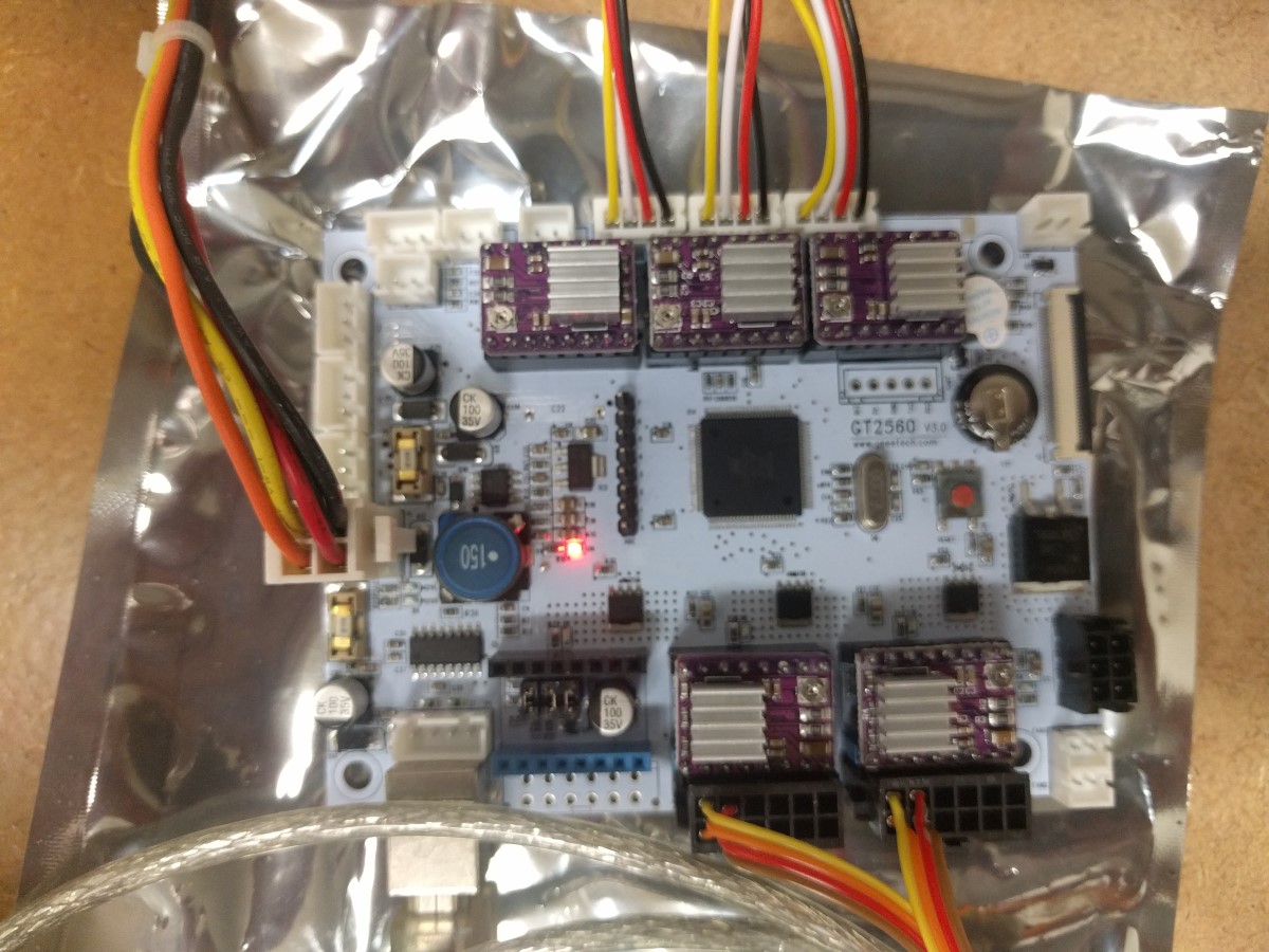
I have connected both Y axis stepper motors to logic board outputs ‘X’ and ‘Y’. As I have not yet flashed the firmware for the GT2560 v3 logic board, so ‘X’ and ‘Y’ need to be driven in pairs in my Gcode. Also, as I haven’t yet set the steps per mm in the firmware, movements may not be true to scale.
The following commands allowed me to carefully test my MPCNC successfully:
G21
G91
G0 F600
G0 Z10
G0 Z-10
G0 X10 Y10
G0 X-10 Y-10
G0 X300 Y 300
G0 X-300 Y-300
G0 F6000
Repeat instructions and experiment with values.
All I had to do was flip one of the stepper motor connectors to make it turn in the opposite direction.
Now it is time to start wiring the stepper motors to the logic board more permanently using crimp connectors and extension leads.
Wiring harness
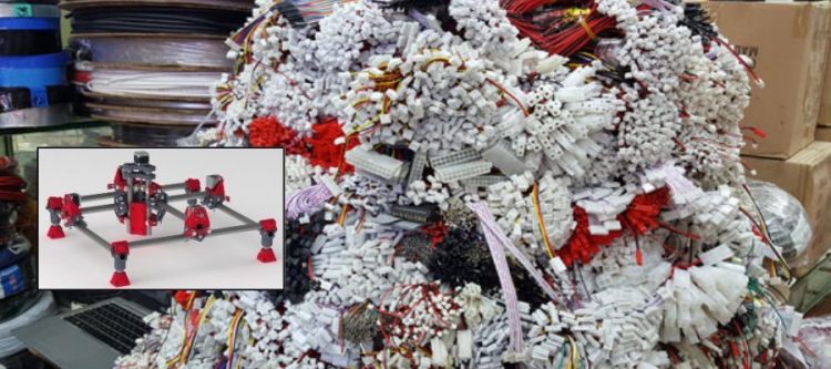
I would have liked to purchase parts from the webshop, but shipping from the US to remote Australia is expensive. So I had to invest in some crimping pliers and various crimp connectors.
http://tech.mattmillman.com/info/crimpconnectors/
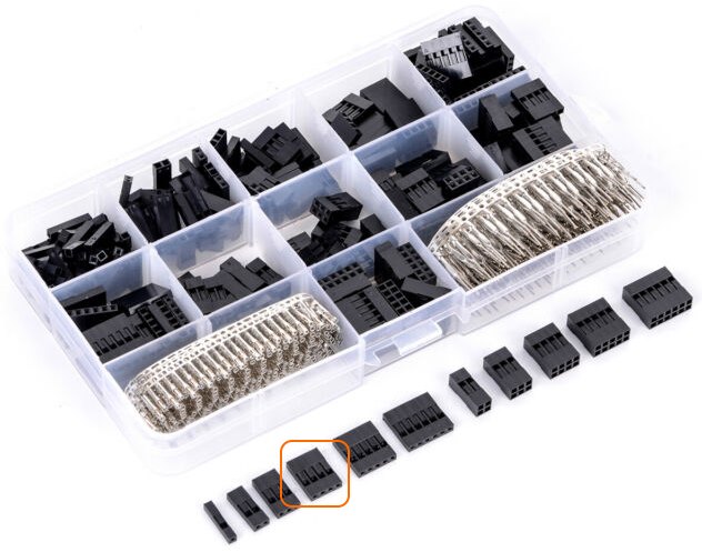
I recommend purchasing a Dupont header connector kit.
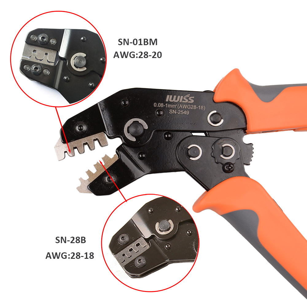
I successfully used long nose pliers to crimp some of my Dupont connectors in combination with a magnifying glass and a sheet of white A4 paper as backdrop for better visibility, but a “SN-28B” model ratchet crimper tool is recommended. I purchased an IWISS “SN-2549” model ratchet crimper tool that has a better quality die set and can crimp AWG18-28 wire connectors.
Higher AWG value = smaller diameter wire: American Wire Gauge (AWG) chart.
NEMA stepper motor wire is about AWG22-24.
Here is a brief instruction video how these type of connectors are crimped (poor quality, mute sound)
https://www.youtube.com/watch?v=n03UMDyQXpE
Crimping Electronics Connectors (Dupont, PH, XH, VH, KF2510)
https://sparks.gogo.co.nz/crimping/index.html
X, Y, Z
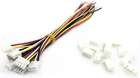
The GT2560 v3.0 logic board uses JST XH 2.5mm pitch 4-pin connectors for the X, Y, and Z axis stepper motor outputs. I ordered some JST XH ‘pigtails’ and crimped Dupont 2.54mm pitch male connectors to the open ends. This allowed me to connect them to the stepper motor leads easily.
(E0), E1, E2
I prefer to connect each stepper to its own output rather than creating a series cabling wiring harness. In my case this means I will have to use the extruder stepper motor connectors, which are connected to Molex Micro Fit 2×6 connectors:
The schematic states pin 1,2,3 and 4 of the Molex Micro Fit 2×6 connectors are used for the stepper motor. The pin numbering does not relate to official Molex Micro Fit 2×6 connector pin numbering however and should be ignored. The correct pinout can be seen in the picture below:
Stepper motor extension leads
You can use 22AWG 5 wire trailer cable, 4 wire security alarm system cable or IPC rainbow flat ribbon cable. I found some 1 meter long 4 pin Dupont extension leads (male to female) on the internet.
Marlin
Steps per mm
A4988 = 1/16th microstepping
DRV8825 = 1/32 microstepping
NEMA17 = 1.8 degrees per step = 360 degrees / 1.8 degrees = 200 steps per revolution
X, Y axis
GT2 Belt pitch = 2mm
Pulley 16T = 16 Teeth
Steps per mm = (Motor Steps per Revolution * Driver Microstep) / (Belt Pitch * Pully Number of Teeth)
Steps per mm (A4988) = (200 * 16) / (2 * 16) = 100
Steps per mm (DRV8825) = (200 * 32) / (2 * 16) = 200
UPDATE: I discovered through trial and error the steps per mm (DRV8825) in my case had to be set to 160.
Z axis
A lot of the leadscrews state they are 2mm pitch, but dont say how many (start) leads they have, most are 4 lead, meaning 4 seperate threads.
T8 leadscrew (8mm diameter, 4 start leads, 2mm pitch)
Steps per mm = (Motor Steps per Revolution * Driver Microstep) / ( Leadscrew Pitch * Start Leads )
Steps per mm (A4988) = (200 * 16) / (2 * 4) = 400
Steps per mm (DRV8825) = (200 * 32) / (2 * 4) = 800
Marlin configuration files
Download either Marlin bugfix 2.0 or V1Engineering’s “Marlin-MPCNC_Rambo_T8_16T_LCD_DualEndstop” which is based on Marlin bugfix 2.0.
https://github.com/MarlinFirmware/Marlin/tree/bugfix-2.0.x
https://github.com/Allted/Marlin/tree/CHOOSE_VERSION
Note that I am using a GT2560 V3 board. The following Marlin files require configuring:
How it works
Marlin firmware is used for 3D printers and more. Marlin will always require at least 1 extruder defined (E0).
#define EXTRUDERS 1
If you use dual steppers to drive a single axis, you will need to define this in the advanced config file:
#define X_DUAL_STEPPER_DRIVERS
#define Y_DUAL_STEPPER_DRIVERS
So instead of single stepper motors driving the X axis and Y axis, we now have two motors driving each axis (X1 + X2 and Y1 + Y2).
Do not specify additional extruders; leave the number of extruders set to 1. Marlin will automatically look for the next extruder E1 and use it as X2. The next extruder E2 is then used as Y2.
I had to change the pinout file so that E0 matches the extruder that does not have a socket soldered on the board (our dummy 3D printer extruder that Marlin needs but is not being used). E1 matches the middle extruder socket on the board and E2 matches the outermost extruder socket on the board.
In the Movement section of the main config file we specify our steps per mm as calculated previously:
//=============================================================================
//============================== Movement Settings ============================
//=============================================================================
// @section motion

/**
 * Default Settings
 *
 * These settings can be reset by M502
 *
 * Note that if EEPROM is enabled, saved values will override these.
 */

/**
 * With this option each E stepper can have its own factors for the
 * following movement settings. If fewer factors are given than the
 * total number of extruders, the last value applies to the rest.
 */
//#define DISTINCT_E_FACTORS

/**
 * Default Axis Steps Per Unit (steps/mm)
 * Override with M92
 *                                      X, Y, Z, E0 [, E1[, E2[, E3[, E4[, E5]]]]]
 */
#define DEFAULT_AXIS_STEPS_PER_UNIT   { 200, 200, 800, 200 }
E0, E1 and E2 will use the same values.
EEPROM
You can tune print settings and store them in EEPROM memory, effectively overriding settings used in the Marlin firmware configuration files.
If you receive a warning message about the EEPROM not matching when you connect to the GT2560 V3 board it is because the EEPROM memory still contains the previous firmware stored values and does not match. We need to overwrite the EEPROM stored values:
M502 = Reset current settings to defaults, as set in Configurations.h

M500 = Store current settings in EEPROM for the next startup or M501.

(M501 = Read all parameters from EEPROM)
So we first load the defaults from the Marlin config file using M502. We then store the values in EEPROM using M500. You can use M501 to read back the stored values if you like.
You should no longer receive warnings about the EEPROM memory not matching the current firmware.
Gcode sample test file
G21
G91
G0 F6000
G0 Z10
G0 X50
G0 Y50
G0 X-50
G0 Y-50
G0 Z-10
M18 ; Disable steppers
M300 S600 P1000 ; Play a 300Hz 1000 millisecond beep
M117 Done! ; Update LCD
The above sample draws a 5cm x 5cm square. Save these Gcode commands in a *.tap file and upload into CNC.js. Press play to run.
Marlin Bug #14743
https://github.com/MarlinFirmware/Marlin/issues/14743
Download bugfix #14743: G53.-.G59.-.G28.zip
This bugfix fixes a problem where entering G54 + G92 X0 Y0 inadvertently also sets a new origin in G53 machine coordinates system.
Cable drag chain
Pipe plug:
https://www.thingiverse.com/thing:3291157
Measuring tape drag chain trick:
https://hackaday.com/2017/12/17/diy-cable-chain-looks-great-stays-cheap/
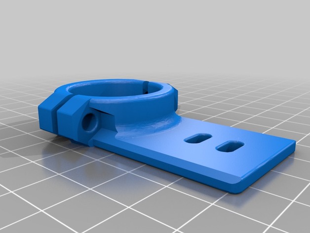
X and Y axis
Instead of using the measuring tape trick I ordered some proper 20×10 drag chain. I printed the following bracket to mount the drag chain to the rollers:
https://www.thingiverse.com/thing:3086172
Drag_chain_mount_for_MPCNC_F25mm.zip
Z axis – measuring tape trick attempt (fail)
To keep the XY gantry as lightweight as possible I decided to use the tape measure trick drag chain:
https://www.thingiverse.com/thing:3395777
MPCNC_Tape_Measure_Trick_-_zip_tie_Z.zip
Cable tie plate bracket to one of the Z axis round tube in between the two Z axis brackets. Cable tie the other end to one of the roller bracket stepper motors.
Measuring tape comes in 13mm (1/2 inch) wide or 25mm (1 inch) wide. I will only run the Z axis stepper through the drag chain; the 240Vac router power lead will hang from the ceiling eventually together with the dust collection hose. I chose 13mm wide measuring tape.
Braided PET (nylon) sleeve diameter is measured as flattended sleeve, not the circumference and comes in widths of 3,6,10,12,20,25,50 mm. I chose 20mm wide braided sleeve.
I should have used 25mm wide measuring tape as the 13mm wide measuring tape was not stiff enough. I also had difficulties strapping it to the stepper motor. All in all my attempt was flimsy and poor quality.
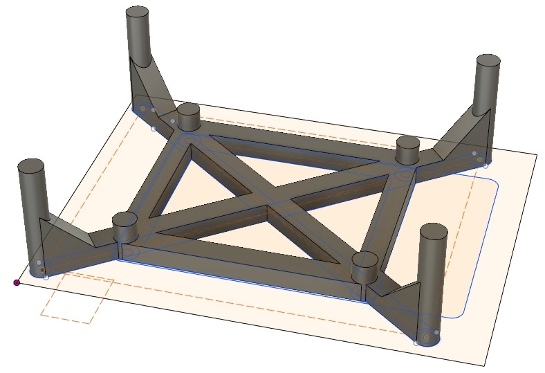
Z axis
I bolted two brackets to the rollers carrying the shortest length round tube on my MPCNC for a drag chain aluminium profile carrying a drag chain:
http://www.thingiverse.com/thing:1855944MPCNC
MPCNC_Braquets_for_aluminium_profile_drag_chain.zip
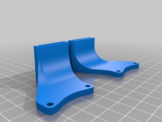
I then purchased a 3 meter length of L strip aluminium 25x20mm 1.5~1.6mm thickness from the hardware store and cut it to length. I had to use slightly longer M3 bolts to secure the brackets to my NEMA17 motors / roller mount.
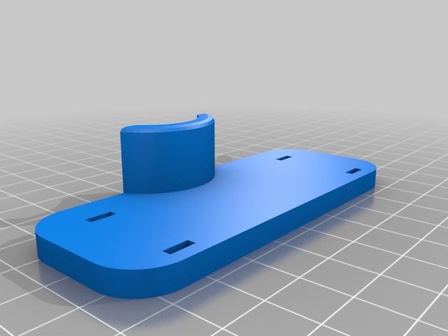
To secure the plastic 20x10mm drag chain to the Z axis I used the following bracket:
http://www.thingiverse.com/thing:3355258
MPCNC_Z_Axis_Cable_Chain_20x10_Mount.zip
I had to add an additional 20mm to the length of the flat strip as the drag chain did not quite reach:
MPCNC_Z_Axis_Cable_Chain_20x10_Mount+20mm.STL.zip
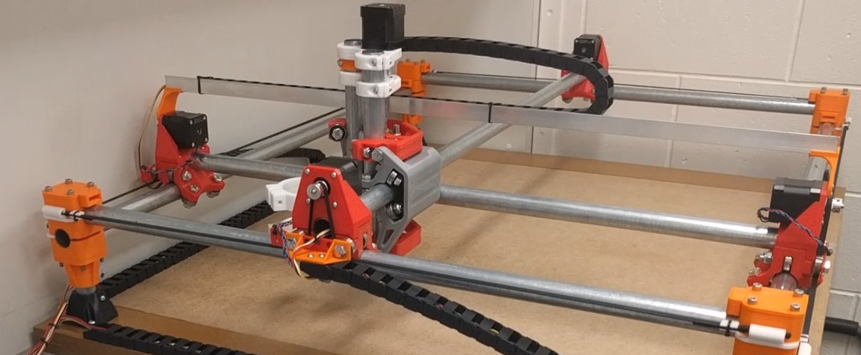
This setup does add some weight to the gantry, but the finish is much cleaner compared to the measuring tape trick. I am happy with the result:
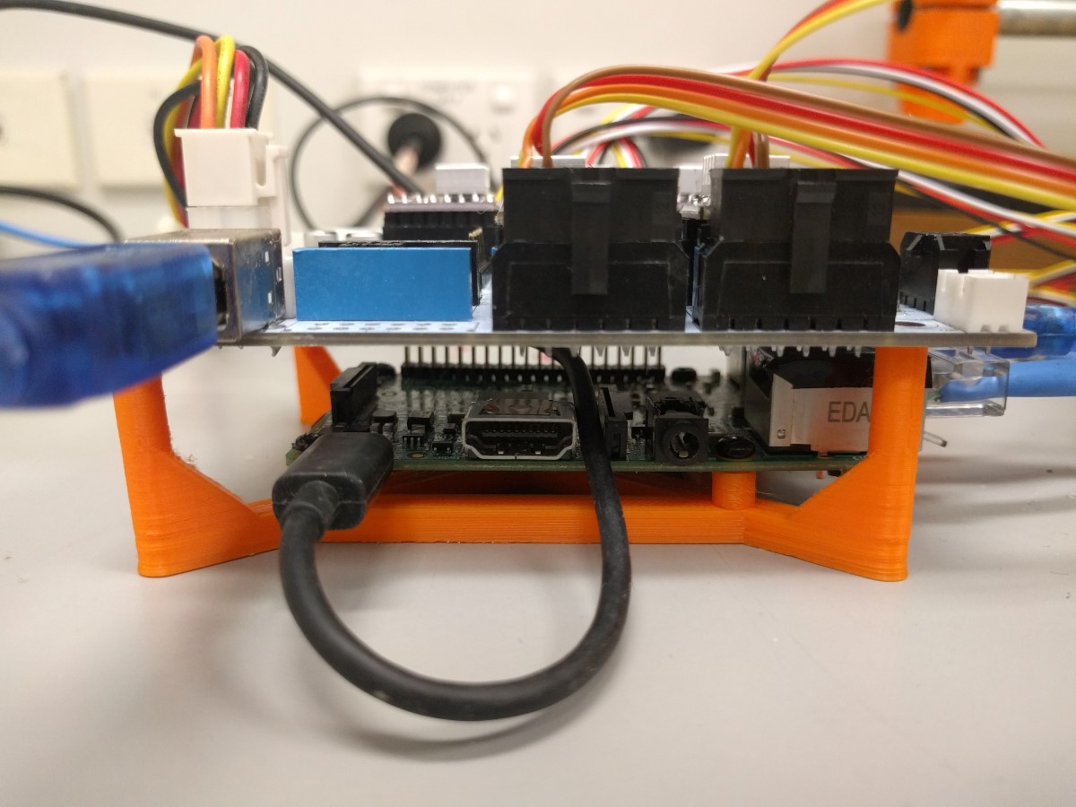
Enclosure
I designed a simple bracket to sandwich the Raspberry Pi and GT2560 V3 board:
I used a hot nail to create holes for some self tapping screws to hold things in place.

After a bit of trial and error I was able to squeeze the electronics into an ATX power supply unit case:
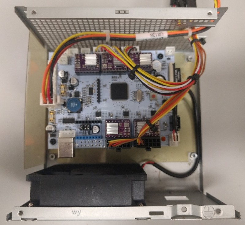
To be honest – I had to flip the board and mount it upside down as the USB connector was interfering with the fan. I then placed the ATX power supply case upside down when assembled. I used a strip of metal to cover the mains socket and power switch.
The final result: