Arduino + Stepper (A3967) EasyStepper
Description
Bipolar stepper motors always have only 4 wires. They require a dual H-bridge to drive them. Bipolar motors offer increased torque compared to unipolar motors. Flyback diodes are required to prevent voltage spikes when the power to the coil is turned off and the stepper motor acts like a generator briefly (back-emf).
Note: You can also connect 5,6 or 8 wire unipolar motors and connect them as bipolar motors by not connecting the common lead(s). They will not have as much torque as bipolar motors due to thinner wire with a higher electrical resistance used in the coils (bifilar windings).
EasyDriver
The EasyDriver is a simple to use stepper motor driver based on an Allegro A3967 chip. It is compatible with anything that can output a digital 0 to 5V pulse (or 0 to 3.3V pulse if you solder SJ2 closed on the EasyDriver). The EasyDriver requires a 6V to 30V supply to power the motor and can power any voltage of stepper motor. The EasyDriver has an on board voltage regulator for the digital interface that can be set to 5V or 3.3V. Connect a 4-wire stepper motor and a microcontroller and you’ve got precision motor control! EasyDriver drives bi-polar motors, and motors wired as bi-polar i.e. 4,6, or 8 wire unipolar stepper motors where the center tap wires are not connected.
This EasyDriver has been co-designed with Brian Schmalz. The microstep select (MS1 and MS2) pins of the A3967 are broken out allowing adjustments to the microstepping resolution. The sleep and enable pins are also broken out for further control.
Note: Do not connect or disconnect a motor while the driver is energized. This will cause permanent damage to the A3967 chip.
Hardware Required
- Arduino Board
- EasyDriver Board
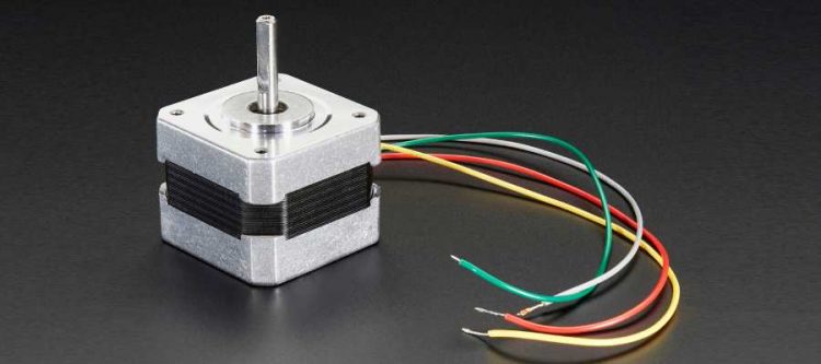
- 4 wire stepper motor (bipolar) i.e. NEMA17
NEMA17 Pinout
NEMA17 4 wire bipolar stepper motor
- 200 steps per revolution, 1.8 degrees
- Adjustable current control from 150mA/phase to 750mA/phase.
- Bipolar stepper, requires 2 full H-bridges!
- 4-wire, 8 inch leads
- 42mm/1.65″ square body
- 31mm/1.22″ square mounting holes, 3mm metric screws (M3)
- 5mm diameter drive shaft, 24mm long, with a machined flat
- 12V rated voltage (you can drive it at a lower voltage, but the torque will drop) at 350mA max current
- 28 oz*in, 20 N*cm, 2 Kg*cm holding torque per phase
- 35 ohms per winding
EasyDriver Pinout
For a detailed description of the EasyDriver pins have a look here:
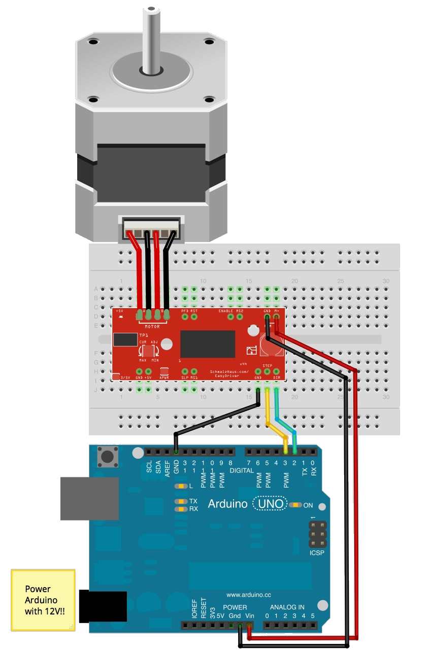
Circuit
(Stepper motor wire colors may vary between models)
Code
/*
Allegro A3967 based EasyStepper board
*/
int dirPin = 2;
int stepperPin = 3;

void setup() {
  pinMode(dirPin, OUTPUT);
  pinMode(stepperPin, OUTPUT);
}

void step(boolean dir,int steps){
  digitalWrite(dirPin,dir);
  delay(50);
  for(int i=0;i<steps;i++){
    digitalWrite(stepperPin, HIGH);
    delayMicroseconds(100);
    digitalWrite(stepperPin, LOW);
    delayMicroseconds(100);
  }
}

void loop(){
  step(true,1600);
  delay(500);
  step(false,1600*5);
  delay(500);
}
Tip: Modifying a 5V 28byj-48 step motor from unipolar to bipolar