Arduino + Analog vs Digital
Digital signals
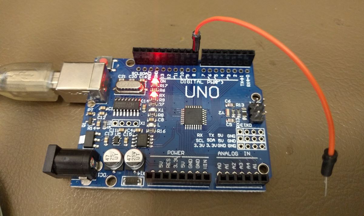
In the Arduino + Pushbutton article we used a pushbutton as an input device connected to a DIGITAL I/O pin. We used internal pull up resistors so that we could connect a pushbutton directly between digital I/O pin 8 and GND.
Circuit
Instead of a pushbutton we can simply connect a wire to pin8 that is connected to GND so simulate a momentary switch or pushbutton.
Code
/*
Important: This example uses active-low logic
*/

int ledPin = 13; // output pin for an onboard LED or external LED
int inPin = 8;   // input pin for a pushbutton
int val = 0;     // variable for reading the pin status

void setup() {
  pinMode(ledPin, OUTPUT);  // declare LED as output
  pinMode(inPin, INPUT_PULLUP);    // declare pushbutton as input + activate internal pull-up resistor
  Serial.begin(9600);
}

void loop(){
  val = digitalRead(inPin);  // read input value
  if (val == LOW) {         // check if the input is LOW (button is active)
    digitalWrite(ledPin, HIGH);  // turn LED on
  } else {
    digitalWrite(ledPin, LOW);  // turn LED off
  }
  Serial.println(val);
}
If we use the Arduino Serial Monitor in the Tools menu we will see something like this:
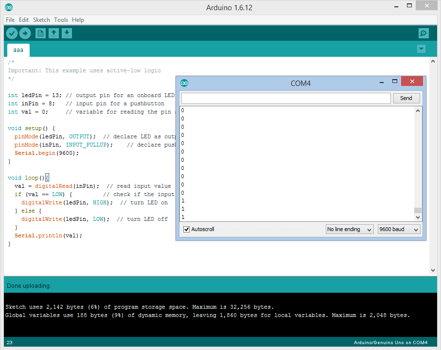
val=0 ; wire is connected to GND
val=1 ; wire is NOT connected to GND
If we use Arduino Serial Plotter in the Tools menu, we will see something like this:
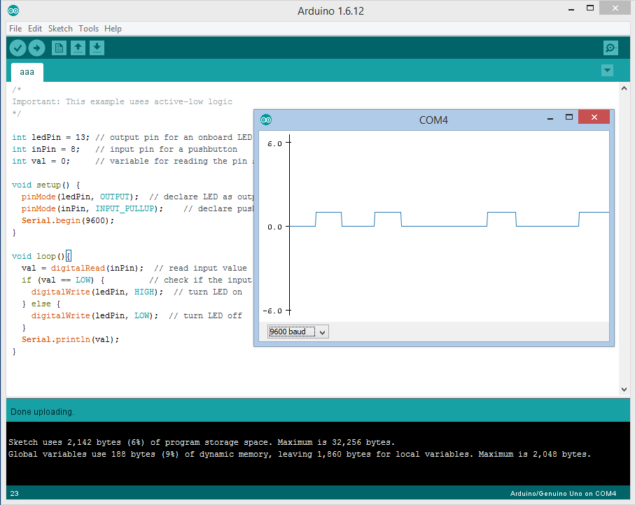
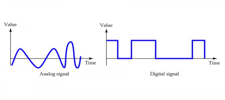
This is a DIGITAL input signal. Arduino microcontrollers treat voltages on a digital I/O pin above +0.7Vdc as HIGH and voltages below +0.3Vdc as LOW. HIGH is represented by a logical ‘one’ and LOW is represented by a logical ‘zero’.
Think of DIGITAL signals as ‘on-off’ pulses. Digital signals can be used for ‘Morse code’ like communications.
So what are ANALOG signals then?
Analog signals
In the Arduino + Potentiometer article we used a potentiometer or variable resistor as an input connected to an ANALOG I/O pin. By varying the voltage on this pin between 0Vdc and +5Vdc the Arduino microcontroller would read this as a value between 0 and 1024.
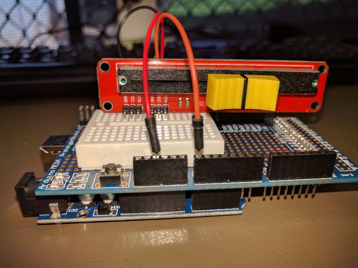
Circuit
Here I have connected a slider potentiometer between GND, +5Vdc where the slider pin is connected to ANALOG I/O pin A0.
Code
int sensorPin = A0;    // select the input pin for the potentiometer
int ledPin = 13;      // select the pin for the LED
int sensorValue = 0;  // variable to store the value coming from the sensor

void setup() {
  // declare the ledPin as an OUTPUT:
  pinMode(ledPin, OUTPUT);
  Serial.begin(9600);
}

void loop() {
  // read the value from the sensor:
  sensorValue = analogRead(sensorPin);
  // turn the ledPin on
  //digitalWrite(ledPin, HIGH);
  // stop the program for <sensorValue> milliseconds:
  //delay(sensorValue);
  // turn the ledPin off:
  //digitalWrite(ledPin, LOW);
  // stop the program for for <sensorValue> milliseconds:
  //delay(sensorValue);
  Serial.println(sensorValue);
}
As the slider is moved, the LED blink pattern will be faster in one direction and slower in the other direction.
If we use the Arduino Serial Monitor in the Tools menu we will see something like this:
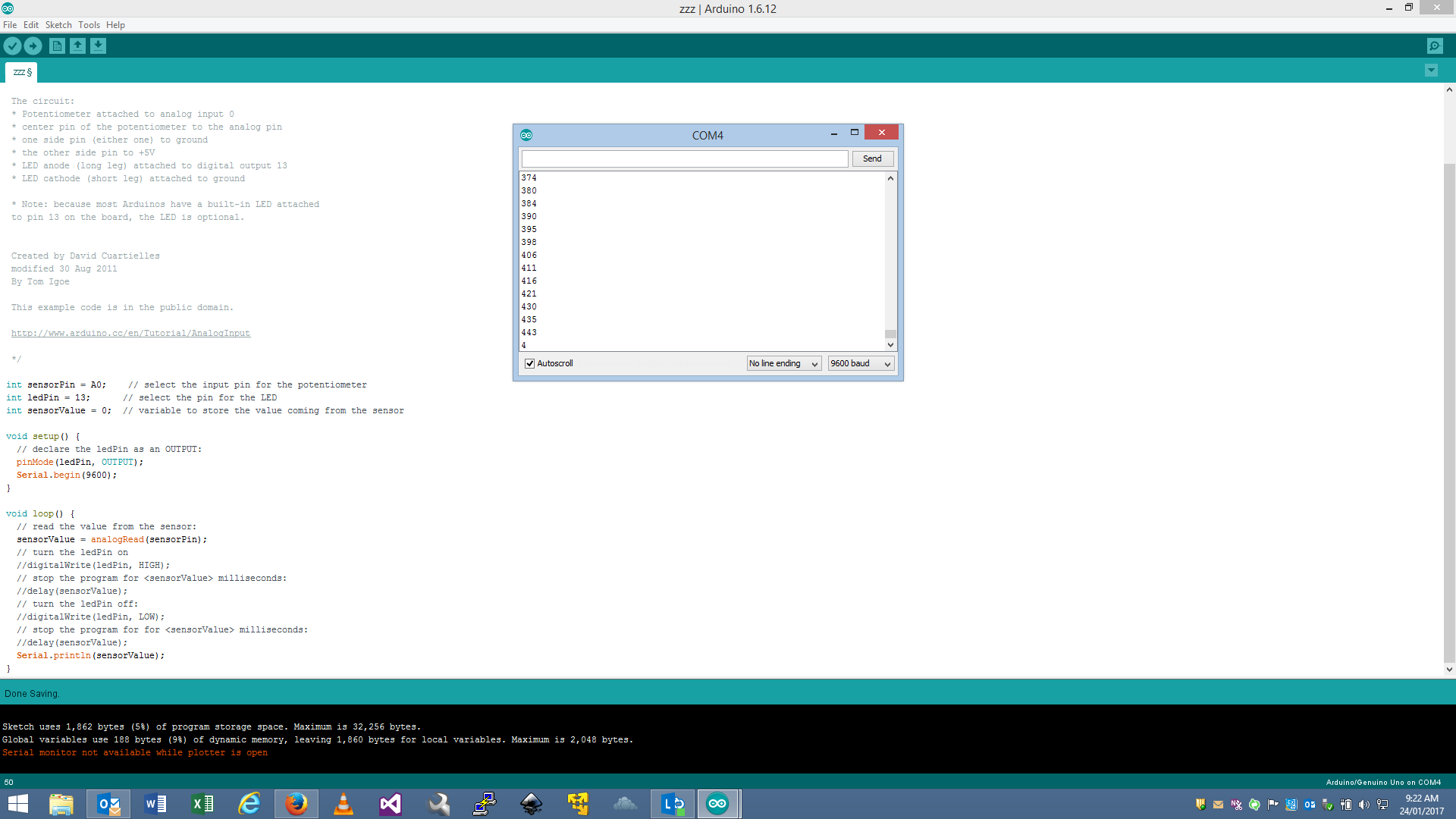
Note that instead of just “0” and “1” we see values ranging from 0 to 1024.
If we use Arduino Serial Plotter in the Tools menu, we will see something like this:
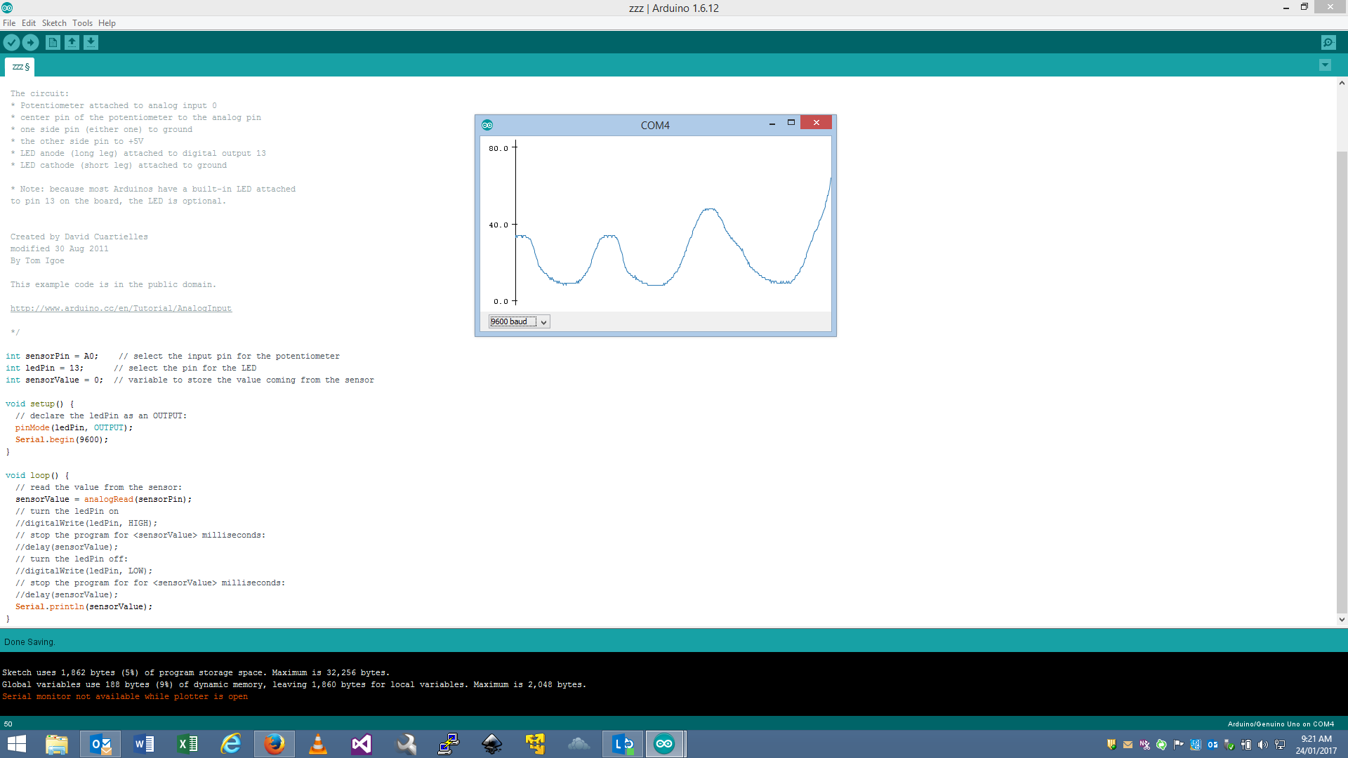
This is an ANALOG input signal. Arduino microcontrollers use analog-to-digital converter circuits to ‘digitize’ measured voltage levels. A voltage level of 0Vdc to +5Vdc can be translated to a number range of 0 to 1024.
Think of ANALOG signals as ‘measurements’; as continuous but often variable signals. Analog signals can be used to measure real-world data like temperature, voltage, pressure, etc. A different type of analog signals are constant sine wave signals. These are characteristic of alternating current or audio spectrum applications.
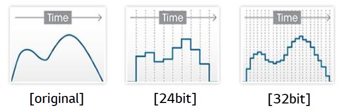
Why are analog I/O pins different from digital I/O pins?
Analog I/O pins are internally connected to an analog-to-digital converter circuit. An analog-to-digital converter ‘approximates’ a smooth analog signal by measuring the voltage level changes. The number of bits an analog-to-digital converter has available for storing samples determines the ‘resolution’ (‘accuracy’) of the analog-to-digital converter.