Arduino + Potentiometer
Description
A switch can be used to make a digital I/O pin LOW or HIGH; a variable resistor or potentiometer can be used to make an analog I/O pin anywhere in between LOW or HIGH. Analog pins recognize voltages between 0Vdc and +5Vdc. This analog voltage between 0Vdc and +5Vdc is then translated to a value between 0 and 1024 respectively.
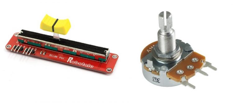
A potentiometer, informally a pot, is a three-terminal resistor with a sliding or rotating contact that forms an adjustable voltage divider. Potentiometers are commonly used to control electrical devices such as volume controls on audio equipment.
Potentiometers are available as (single turn or multiple turn) rotary potentiometers or sliding potentiometer.
The relationship between slider position and resistance, known as the “taper”, is controlled by the manufacturer. In principle any relationship is possible, but for most purposes linear or logarithmic (aka “audio taper”) scale potentiometers are used.
Hardware Required
- Arduino board
- 10kOhm linear potentiometer (rotary single turn or slider).
Circuit
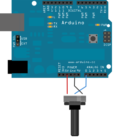
We can connect the slider of a rotatary potentiometer to analog pin A0 like so:
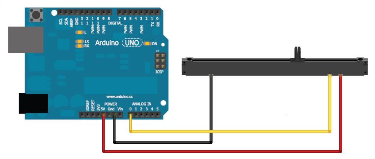
Or we can connect the slider of a linear potentiometer to analog pin A0 like so:
Note that input pins are ‘high-impedance’. This means they will not draw much current and as a result their impact on a circuit is negligable. By connecting a 10kOhm potentiometer between GND and +5V a current of 0.5mA will flow; the current absorbed by the input pin via the slider is magnitudes smaller and as such negligable. If the slider is located closest to GND terminal, the slider will read 0V. If the slider is located closest to the +5Vdc terminal, it will read +5Vdc. Anywhere in between, the slider will read a voltage in line with its position (move slider to one fifth position = 1Vdc, move slider halfway = 2.5Vdc, move slider to four fifths position = 4Vdc).
Code
/*
  Analog Input
 Demonstrates analog input by reading an analog sensor on analog pin 0 and
 turning on and off a light emitting diode(LED)  connected to digital pin 13.
 The amount of time the LED will be on and off depends on
 the value obtained by analogRead().

 The circuit:
 * Potentiometer attached to analog input 0
 * center pin of the potentiometer to the analog pin
 * one side pin (either one) to ground
 * the other side pin to +5V
 * LED anode (long leg) attached to digital output 13
 * LED cathode (short leg) attached to ground

 * Note: because most Arduinos have a built-in LED attached
 to pin 13 on the board, the LED is optional.


 Created by David Cuartielles
 modified 30 Aug 2011
 By Tom Igoe

 This example code is in the public domain.

 http://www.arduino.cc/en/Tutorial/AnalogInput

 */

int sensorPin = A0;    // select the input pin for the potentiometer
int ledPin = 13;      // select the pin for the LED
int sensorValue = 0;  // variable to store the value coming from the sensor

void setup() {
  // declare the ledPin as an OUTPUT:
  pinMode(ledPin, OUTPUT);
}

void loop() {
  // read the value from the sensor:
  sensorValue = analogRead(sensorPin);
  // turn the ledPin on
  digitalWrite(ledPin, HIGH);
  // stop the program for <sensorValue> milliseconds:
  delay(sensorValue);
  // turn the ledPin off:
  digitalWrite(ledPin, LOW);
  // stop the program for for <sensorValue> milliseconds:
  delay(sensorValue);
}
As the value of the potentiometer changes, the LED blink pattern will change; lower values result in a fast blink pattern and higher values will result in a slower blink pattern.
Tip: You can send the ‘sensorValue’ variable to the Arduino Serial Monitor using serial communication if you would like to see the actual value.