Arduino + Pushbutton
Description
There are a number of digital I/O pins on the board that can be used as a digital input or digital output. If a digital I/O pin is used as an output, you can make a pin HIGH (5V) or LOW (0V) to drive LEDs, servos, LCD displays, etc. If a digital I/O pin is used as an input, the Arduino can probe the pin. It will register either a LOW if the voltage is below 1.5V or a HIGH if the voltage is above 3V. If the voltage on the pin is somewhere in between you will experience erratic behavior where sometimes a LOW is registered and sometimes a HIGH due to residual charge (hysteresis).
Switches
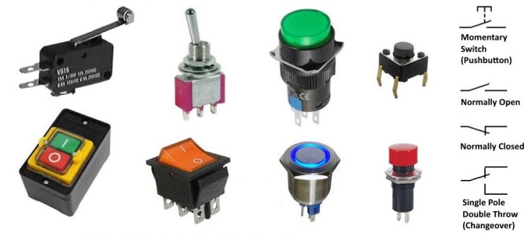
There are a different types of switches:
Momentary Switches – Only engaged while it is being depressed (i.e. pushbutton)
Latching Switches – Remains engaged when no longer depressed
Normally Open – Contacts are open when in rest.
Normally Close – Contacts are closed when in rest.
Single Pole Double Throw (SPDT) – Typical On/Off toggle switch. When one contact is closed the other contact opens. This type of switch has 3 contact pins instead of 2.
Pushbutton
The most popular common digital input is a momentary pushbutton. Let’s have a closer look.
Hardware Required
- Arduino Board
- Momentary pushbutton
Circuit
The wrong way to connect a pushbutton to an Arduino is this:
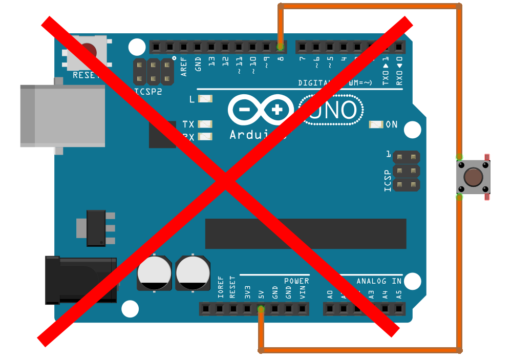
The problem with this circuit is that when the pushbutton is in rest, the voltage on pin8 is not defined (floating). Any static charge the wire picks up from its surroundings or any residual charge in the Arduino might cause the pin to read as HIGH or LOW. Any erratic behavior where a pin goes HIGH or LOW for no apparent reason is often caused by a floating pin; a pin that does not have a defined voltage level.
The right way to connect a momentary pushbutton is as follows:
Pull-down resistor
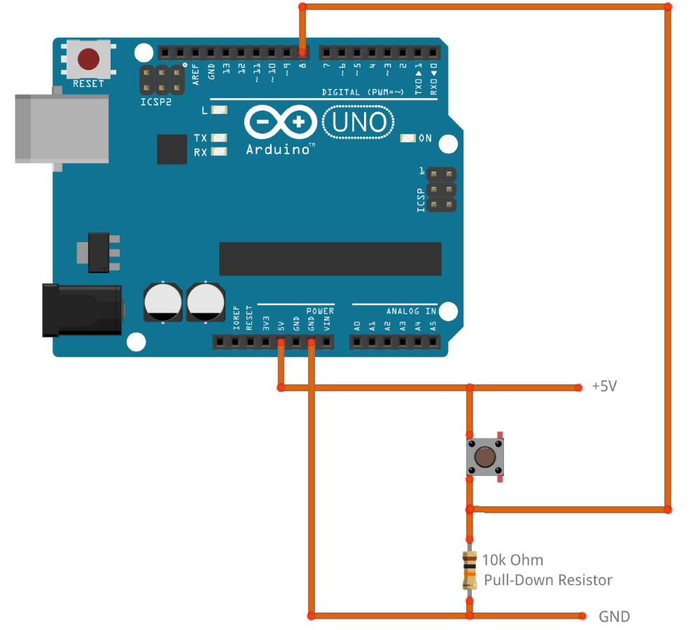
When the pushbutton is idle, there is no current flowing. The resistor acts like a short to ground. The pushbutton acts like an open connection. The voltage potential on pin 8 is 0V (GND).
To understand the next step, it helps to know that an Arduino input current draw is almost nil. Inputs in TTL type logic are designed to have high impedance which means they draw minimal current. TTL logic gates can be considered to have no impact on the operation of a circuit and will simply take on the voltage potential of whatever it is they are connected to.
When the pushbutton is active, there is current flowing from the +5V rail, through the pushbutton (short) through the resistor to the ground rail (0V). Due to the resistor having a high value, the current is limited to only 0.5mA. Pin 8 is now effectively connected to the +5V rail and the Arduino will register the input as HIGH instead of LOW.
Pull-up resistor (‘Active low’ logic)
For applications where safety is paramount you may want to invert the logic and have the Arduino register HIGH when the pushbutton is idle. Using the circuit below, the resistor will cause pin8 to be pulled up to the +5V rail and register as HIGH when the pushbutton is not in use and no current is flowing. By pressing the pushbutton, pin8 will be connected to the ground rail (0V) and register as LOW.
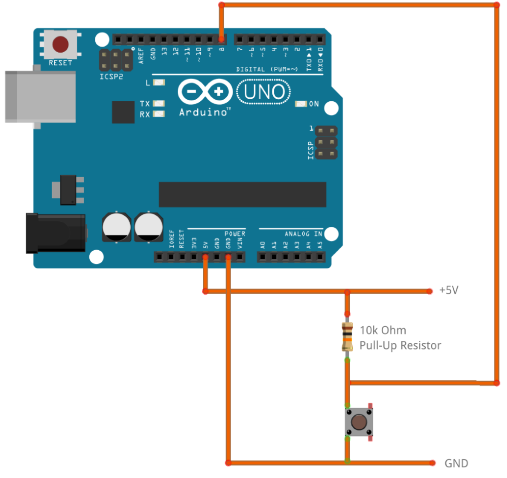
Circuits where the logic is HIGH when idle and LOW when active are referred to as ‘active low’ logic. The benefit of using ‘active low’ logic is that a fault in a component will result in the Arduino registering this as a constant active pin and being able to take corrective action (i.e. halt operation in a safe manner).
Note the pull-down resistor we used previously is now acting as a pull-up resistor, connecting pin 8 to the +5V rail when idle.
For now, let’s use the first circuit (the one with the pull-down resistor) and write some code.
Code
int ledPin = 13; // output pin for an onboard LED or external LED
int inPin = 8;   // input pin for a pushbutton
int val = 0;     // variable for reading the pin status

void setup() {
  pinMode(ledPin, OUTPUT);  // declare LED as output
  pinMode(inPin, INPUT);    // declare pushbutton as input
}

void loop(){
  val = digitalRead(inPin);  // read input value
  if (val == HIGH) {         // check if the input is HIGH (button is active)
    digitalWrite(ledPin, HIGH);  // turn LED on
  } else {
    digitalWrite(ledPin, LOW);  // turn LED off
  }
}
Internal pull-up resistors
Remember the wrong way to connect a pushbutton? Here is a little trick; we can connect a pushbutton directly to GND and pin8 without using a pull-up resistor. The Atmega microcontroller on the Arduino has internal pull-up resistors (resistors that connect to power internally) that you can access. If you prefer to use these instead of external pull-up resistors, you can use the INPUT_PULLUP argument in pinMode().
This is how it works: 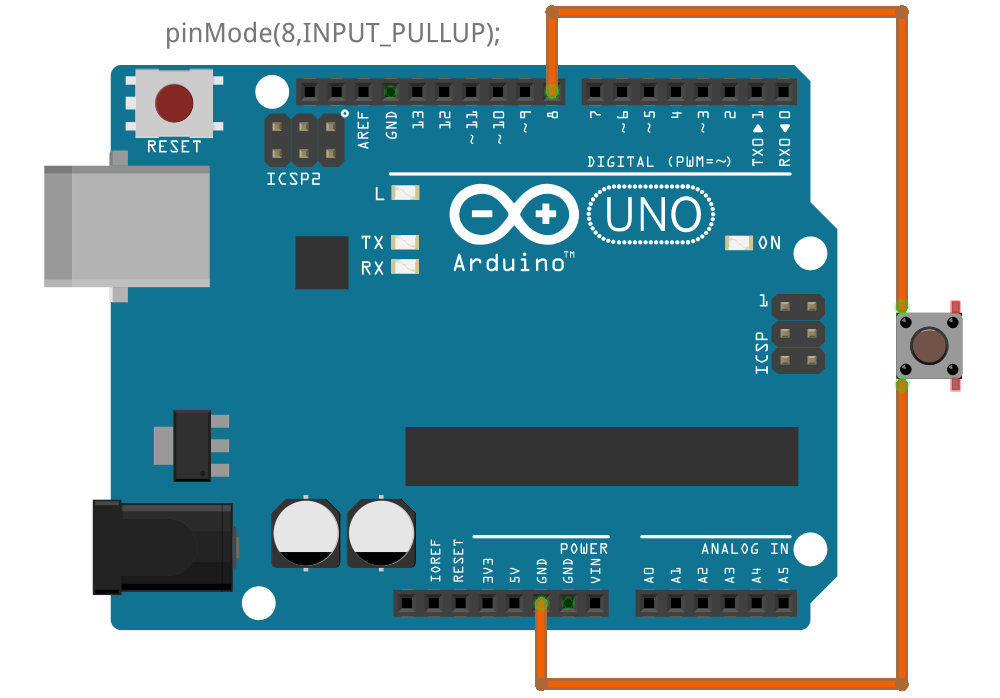
Note the pushbutton is connected to GND similar. The resistor connected between the pushbutton and +5V rail is now replaced by an internal resister inside the Arduino.
/*
Important: This example uses active-low logic
*/

int ledPin = 13; // output pin for an onboard LED or external LED
int inPin = 8;   // input pin for a pushbutton
int val = 0;     // variable for reading the pin status

void setup() {
  pinMode(ledPin, OUTPUT);  // declare LED as output
  pinMode(inPin, INPUT_PULLUP);    // declare pushbutton as input + activate internal pull-up resistor
}

void loop(){
  val = digitalRead(inPin);  // read input value
  if (val == LOW) {         // check if the input is LOW (button is active)
    digitalWrite(ledPin, HIGH);  // turn LED on
  } else {
    digitalWrite(ledPin, LOW);  // turn LED off
  }
}
Although this trick is very clever, the only saving is a (10 cent) resistor. The downside is that you could easily miss the fact this circuit requires internal pull-up resistors to work properly. Also, this only works for “active low” logic as the Arduino does not have internal pull-down resistors; only internal pull-up resistors.
Debounce
Arduino microcontrollers run at 16Mhz. They can process several million instructions per second! Like a child repeatedly asking “Are we there yet?”, an Arduino microcontroller can probe a pushbutton a million times per second to check “Is the pushbutton being depressed yet?”. For a microcontroller, everything in real life would appear as if it is running in slow-motion.
If you think of somebody depressing a pushbutton in slow-motion, you can see how a pushbutton would not make perfect contact instantly. Pushbuttons often generate spurious open/close transitions when pressed, due to mechanical and physical issues: these transitions may be read as multiple presses in a very short time fooling the program.
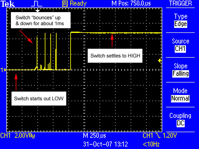
This example demonstrates how to debounce an input, which means checking multiple times in a short period of time to make sure the pushbutton is definitely pressed. Without debouncing, using any type of switch is likely to cause unpredictable results.
Using the 10kOhm pull-down resistor and pushbutton circuit we can write the following code:
int ledPin = 13; // output pin for an onboard LED or external LED
int inPin = 8;   // input pin for a pushbutton
int val1 = 0;     // variable for reading the pin status
int val2 = 0;    // variable for reading the pin status

void setup() {
  pinMode(ledPin, OUTPUT);  // declare LED as output
  pinMode(inPin, INPUT);    // declare pushbutton as input
}

void loop(){
  val1 = digitalRead(inPin);  // read first input value
  delay(50);    // 50 millisecond delay
  val2 = digitalRead(inPin);  // read second input value
  if (val1 == val2) {    // make sure we have a stable button state
    if (val1 == HIGH) {         // check if the input is HIGH (button is active)
      digitalWrite(ledPin, HIGH);  // turn LED on
    } else {
      digitalWrite(ledPin, LOW);  // turn LED off
    }
  }
}
Rather than using a delay, a more elegant way would be to keep testing the button continuously. Suppose the latest valid pushbutton state was “LOW”. Then all of a sudden you measure a “HIGH”. If you now measure 50xHIGH in a row, then the switch contact is stable – we have a valid input. The latest valid pushbutton state is now changed from “LOW” to “HIGH”.
For this to work you will need a variable “laststate” to keep track of the most recent valid state.
This method will work faster. However, if you are not in a hurry and can simply wait 50 milliseconds to make sure any bouncing of the switch would have passed and read the switch value again, that might be the simplest solution.