Arduino + Servo (or ESC)
Description
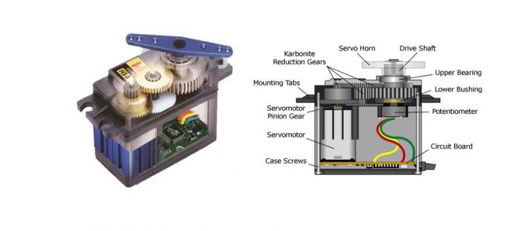
The Arduino servo library allows an Arduino board to control RC (hobby) servo motors. Servos have integrated gears and a shaft that can be precisely controlled. Standard servos allow the shaft to be positioned at various angles, usually between 0 and 180 degrees. Continuous rotation servos allow the rotation of the shaft to be set to various speeds.
Pinout
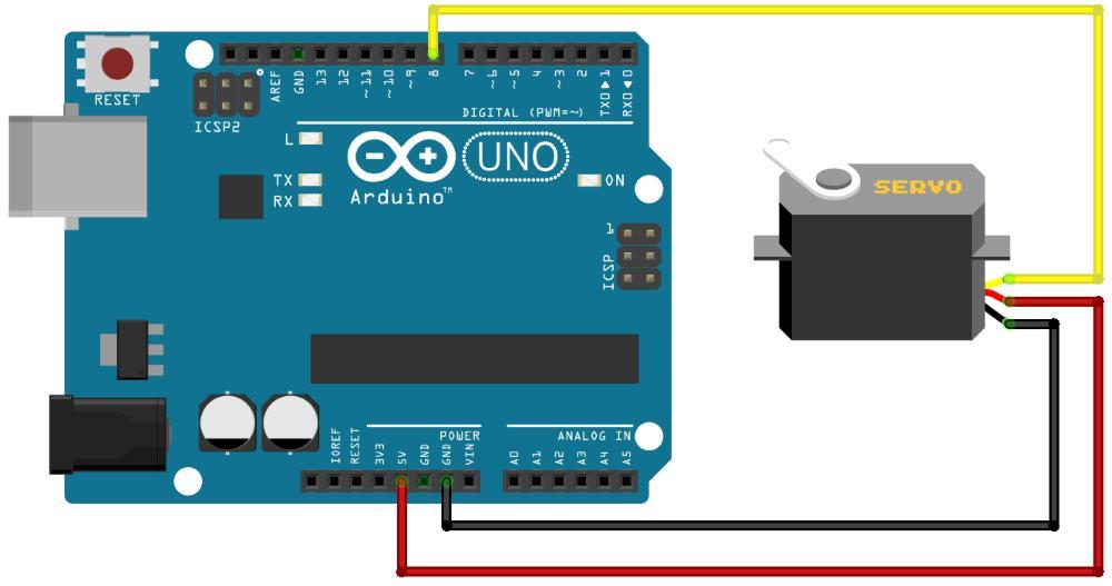
Servo motors have three wires: power, ground, and signal.
- Red – Power (+5V)
- Black or Brown – Ground (0V)
- Yellow, Orange or White – Signal – 5V block wave – 20ms period time(50Hz)
Note that servos draw considerable power, so if you need to drive more than one or two, you’ll probably need to power them from a separate supply (i.e. not the +5V pin on your Arduino). Be sure to connect the grounds of the Arduino and external power supply together to ensure a common ground.
Common Ground
Voltage is not an absolute value of a single point in a circuit. Instead, it is measured on an interval scale, which means that only differences can be measured. To measure the voltage of a single point, a reference point must be selected to measure against. This common reference point is called “ground” and considered to have zero voltage. To connect two different circuits together it is good practice to connect the grounds together so that all voltage differences are measured relative to the same reference.
Servos
The position of the servo motor is set by the length of a pulse. The servo expects to receive a pulse roughly every 20 milliseconds (50Hz). If that pulse is high for 1 millisecond, then the servo angle will be zero, if it is 1.5 milliseconds, then it will be at its centre position (90 degrees) and if it is 2 milliseconds it will be at 180 degrees.

Voltages, pulse widths and end points vary between servos and many servos only turn through about 170 degrees. If you need a high degree of precision stepper motors might be a more suitable option.
Hardware Requirements
- Arduino Uno
- Servo
Circuit
Code
Example 1
/*
 Servo Basics

 Demonstrates the use of a servo.

 This sketch centers a servo.

  The circuit:
 * Servo connected to pin 8

 This example code is in the public domain.

 */

#include <Servo.h>

Servo myservo;  // create servo object to control a servo
                // a maximum of eight servo objects can be created

int pos = 90;    // variable to store the servo position

void setup()
{
  myservo.attach(8);  // attaches the servo to pin 8
}

void loop()
{
  myservo.write(pos);              // tell servo to go to position in variable 'pos'
}
Example 2
// Sweep
// This example code is in the public domain.

#include <Servo.h>

Servo myservo;  // create servo object to control a servo
                // a maximum of eight servo objects can be created

int pos = 0;    // variable to store the servo position

void setup()
{
  myservo.attach(8);  // attaches the servo on pin 8
}


void loop()
{
  for(pos = 0; pos <= 180; pos += 1)  // goes from 0 degrees to 180 degrees
  {                                  // in steps of 1 degree
    myservo.write(pos);              // tell servo to go to position in variable 'pos'
    delay(15);                       // waits 15ms for the servo to reach the position
  }
  for(pos = 180; pos >= 1; pos -= 1)     // goes from 180 degrees to 0 degrees
  {
    myservo.write(pos);              // tell servo to go to position in variable 'pos'
    delay(15);                       // waits 15ms for the servo to reach the position
  }
}
Example 3
/* Control a servo using a potentiometer
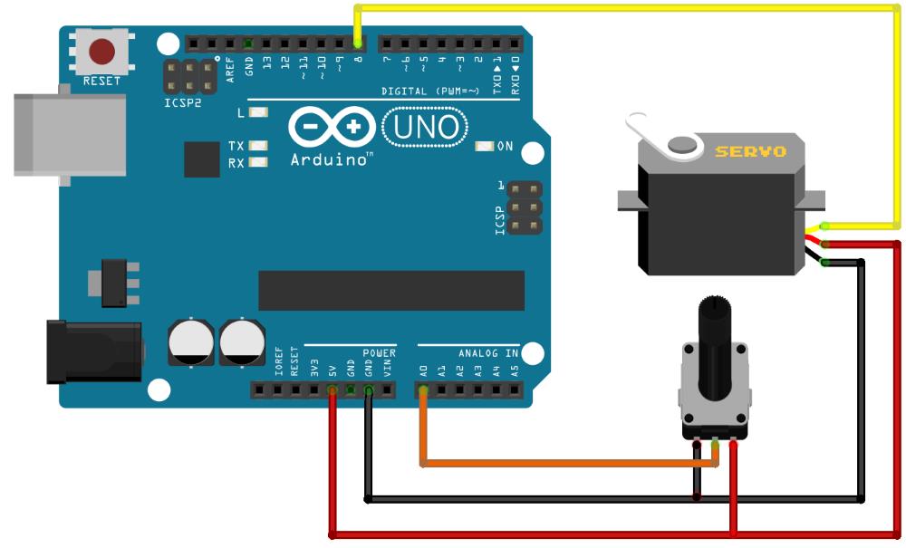
The circuit:
* Potentiometer attached to analog input 0
* center pin of the potentiometer to the analog pin
* one side pin (either one) to ground
* the other side pin to +5V
* Servo connected to digital pin 8
This example code is in the public domain.
*/
#include <Servo.h>
Servo myservo; // create servo object to control a servo
// a maximum of eight servo objects can be created
int posValue = 0; // variable to store the servo position
int sensorPin = A0; // select the input pin for the potentiometer
int sensorValue = 0; // variable to store the value coming from the sensor
void setup()
{
myservo.attach(8); // attaches the servo on pin 8 to the servo object
Serial.begin(9600); // configure serial port to use 9600 bps
Serial.println("---start---");
}
void loop()
{
sensorValue = analogRead(sensorPin);
posValue = map(sensorValue, 0, 1023, 0, 180);
// print the results to the serial monitor:
Serial.print("sensor = " );
Serial.print(sensorValue);
Serial.print("\t servo position = ");
Serial.println(posValue);
myservo.write(posValue); // tell servo to go to position in variable 'pos'
}
Using an Electronic Speed Control (ESC) and brushless outrunner DC motor.
If you are familiar with remote control (RC) cars or airplanes you probably already know you can use an Electronic Speed Controller (ESC) and connect it to a LiPo battery and DC motor. The signal line would normally plug into the remote control receiver Throttle channel and would receive servo signals from the transmitter (throttle stick).
As the ESC connects to a servo signal channel on the receiver, you can actually just the same connect the ESC to your Arduino. Simply send the ESC a servo signal and use a LiPo battery to drive a brushless DC outrunner motor. This allows for precise speed control including forward and reverse.