Kerbal Space Program – How to build a rocket
What engines to use? How much fuel to take? What shape should the craft be? Stack decouplers or Radial decouplers? Solid booster or Liquid Fuel Engine? Let’s start with some basic concepts.
Basic concepts
Forces
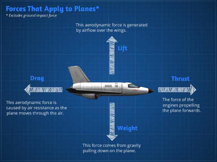
There are four forces acting on a craft when in the lower atmosphere within gravity: Thrust, Weight, Lift and Drag.
Thrust and Lift = Good.
Drag and Weight = Bad, although they do come in handy at times.
Forces during atmospheric vertical take-off.
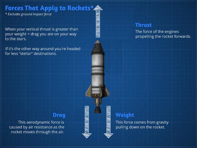
Forces during angled atmospheric flight
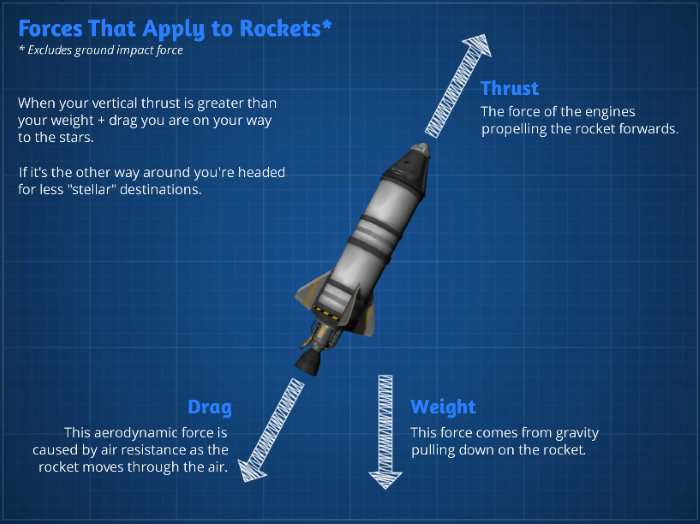
In space, there is only Thrust and the Gravitational pull from planets.
Before we start looking at these forces, let’s get something out of the way first.
Mass versus Weight
Objects have mass. It is a property of an object. Mass is measured in kilograms. Thousand kilograms is called one ton or tonne (1t).
Weight is an indicator of how heavy an object ‘feels’. Even though on earth we express weight in kilograms, it really should be expressed as a force in Newton (N).
The Moon’s gravity is 1/6th that of Earth’s gravity. The force exerted by a 50kg ACME anvil dropped on Wile E. Coyote is 6 times less on the Moon than on Earth.
As I am not likely to leave the planet anytime soon kilograms will do just fine; 1kg weighs not much really, 10kg weighs quite a bit more and 1000kg weighs a lot. For interplanetary rocket design, we need to be more accurate, so:
- Mass is a property (kg).
- Weight is a force (N) and represented by a vector.
Hint If you see the word ‘weight’, simply substitute it for ‘force of gravity’. Let’s agree not to use the word ‘weight’ anymore. Either use ‘mass’ or ‘(force of) gravity’, but definitely not ‘weight’, okay?
Now we can look at forces acting on a craft in atmosphere (aerodynamic forces of lift and drag) under gravity (force of gravity) using its engines (force of thrust). A force is a vector; it acts on a center and pushes in a certain direction with a certain amount. Vector. Center. Direction. Amount.
Let’s look at the various centers and vectors next.
Center of Mass (CoM) – Indirectly represents the Gravity Force Vector
Balance an object on the tip of your finger.
The point in space where your finger is placed to balance the object is where the center of mass is located.
(!) The Center of Mass of an object is a static property of an object. It is also where the downward force of gravity pulls down on the rocket or plane. Hence it indirectly resembles the center on which the downward force of gravity acts.
Center of Thrust (COT) – Thrust Force Vector
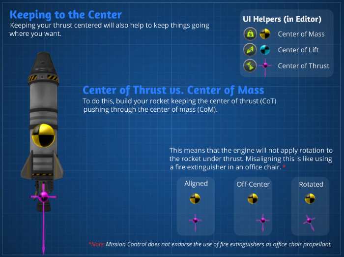
The center of thrust is displayed as a vector. It is the midpoint where thrust from engines balances and the direction in which it is acting. It is often called the thrust vector. For your typical rocket, COT sits perfectly centered at the base of the rocket behind a perfectly centered COM perfectly in line with the centerline of the rocket. Perfect.
Center of Lift (COL) – Lift Force Vector
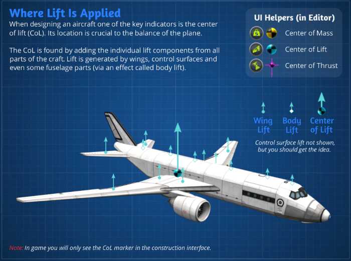
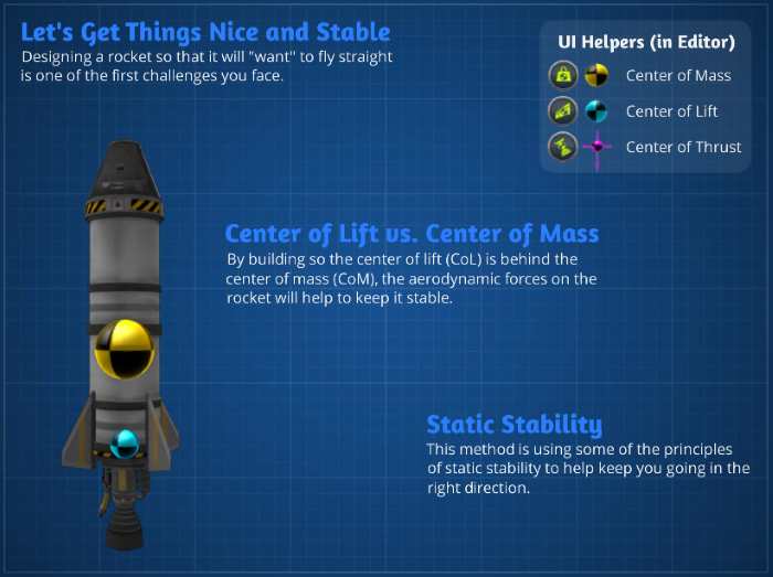
The center of lift is the point where the sum total of all lift generated by parts — principally by wings, control surfaces, and aerodynamic fuselage parts — balances out and the aggregate direction their force will act on a craft while in an atmosphere. Has nothing to do with with engines / thrust.
Drive in a car.
Hold your hand out of the car window.
Hold your hand horizontal with your finger tips pointing into the wind.
Angle your hand up slightly. Positive lift.
Angle your hand down slightly. Negative lift.
Flight Characteristics of an airplane:
- COL ahead of COM → Flips or turns uncontrollably
- COL inside COM → Excessively maneuverable; needs constant course correction
- COL closely behind of COM → More maneuverable
- COL further behind of COM → More stable
- COL very far behind of COM → Very hard to correct course; likely to flip up or nosedive
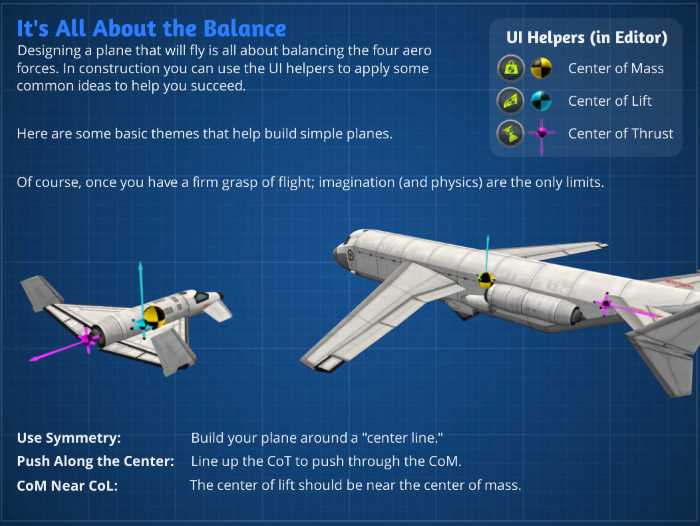
For both rockets and airplanes we have to line up the COT to push through the COM. If the COT and COM are not perfectly aligned, the craft will pivot around the COM.
COL ↔ Rockets
Rockets don’t glide gently through the air like an airplane. Rockets use massive amounts of thrust to punch a hole through the atmosphere to go up. The only surfaces on a rocket that could potentially create lift are the stabilization fins at the base of a rocket. And these are not angled to create lift; they are perfectly in line and only used to create drag for passive stability. For rockets the center of lift is typically located in the center of the stabilization fins at the base of the rocket. These fins are oriented perfectly straight and in a symmetrical fashion so that they do not generate lift, only drag. The only time a rocket generates lift is when the control surfaces on individual stabilization fins are used to make course corrections whilst in the atmosphere. In space we need to use small thrusters mounted in/on the hull to perform course corrections.
COD (Center of Drag)
Sum of all drag generated by parts. It exists, but we don’t care much because as long as you make things pointy and narrow, this force is much smaller than any of the other forces anyway.
Let’s focus on rockets exclusively from here on out.
Basic concepts of rockets
Payload – The final stage. Everything that is not decoupled and jettisoned. Also known as cargo. Less is better.
Thrust to Weight Ratio (TWR) – Ratio that defines the power of a craft’s engines in relation to its weight.
The Center of Mass is where gravity pushes down. The force of gravity is (unfortunately) named ‘weight’. The Center of Thrust is where the engines push up. The force generated by the engines is named ‘thrust’. Hence Thrust To Weight ratio. This is what the TWR factor indicates.
You need a TWR of >1.0 (more thrust than gravity) for a rocket to take-off. A TWR of about 1.4 for low atmosphere stages is good. After that it can be a little lower, but generally keep it above 1.0.
TWR is only relevant when trying to overcome gravity (take-off and landing); it tells us if something will go up or come down.
Note though that TWR varies with gravity. A rocket with a TWR of 1.14 at sea level on Kerbin will have a TWR of 7.34 on the surface of the Mun. So to take off from the Mun you can use much smaller engines than to take off from Kerbin.
It is called Thrust to Weight ratio and not Thrust to Mass ratio for a reason. Thrust is a force. Weight is a force (the force of gravity acting on mass). Mass is simply a property of an object.
Delta V (ΔV) – The increase in speed (‘impulse’) required to escape the gravitational pull of an object.
The speed you are traveling at can be considered an impulse. To escape a certain gravity, a specific speed is required. If we start from standstill, ΔV simply is the speed we reach after exhausting all our fuel at full thrust in a vacuum. If we already have a start velocity, we can simply subtract this from the ΔV required. If we have to overcome multiple gravitational bodies we can simply add up the required ΔV for each body. The ΔV for a multi-stage rocket is the sum of the ΔV for each stage. ΔV is typically calculated in a vacuum.
Specific Impulse (Isp) – Engine efficiency
It is no surprise the ratio between fueled weight of a rocket (stage) versus dry weight (no fuel) is a factor in how much impulse (ΔV) a rocket (stage) can generate. But the efficiency of the engine also has a role to play. This is Isp. A measure of the efficiency of an engine and acts as a simple multiplication factor.
Note that the Isp at sea level in thick atmospheres is different than Isp in space (near vacuum). Some engines are better suited as booster (high Isp at sea level), some as second or third stage (high Isp in near vacuum).
Aerodynamic Forces or Drag – Resistance from air when moving in a thicker atmosphere.
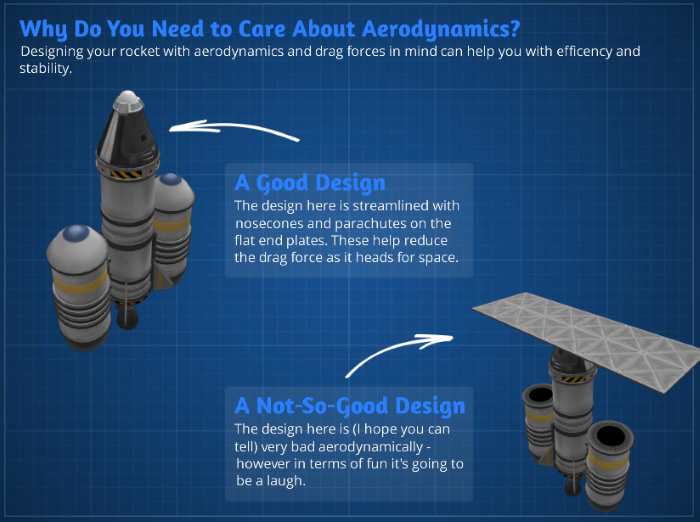
Pointy shaped = good. Blunt shaped = bad. Narrow = good. Wide = bad.
Stability
The aerodynamic flight characteristics of a rocket in flight in atmosphere is referred to as ‘stability’. A rocket is like balancing a pencil on the tip of your finger. So what makes a rocket stable in low atmospheric flight you might wonder?
Rockets are an inverted pendulum;
Tall pendulum = bad; tips over easily.
Short pendulum = bad; nervous, tendency to overcompensate.
Drag and stability are often at odds. Narrow and pointy is good for drag, but narrow and pointy equals tall and tall is very bad for stability. So we need to sacrifice some drag to gain a lot of stability at some point. Three stages using stack decouplers will benefit from radial decouplers for a next stage.
Symmetry
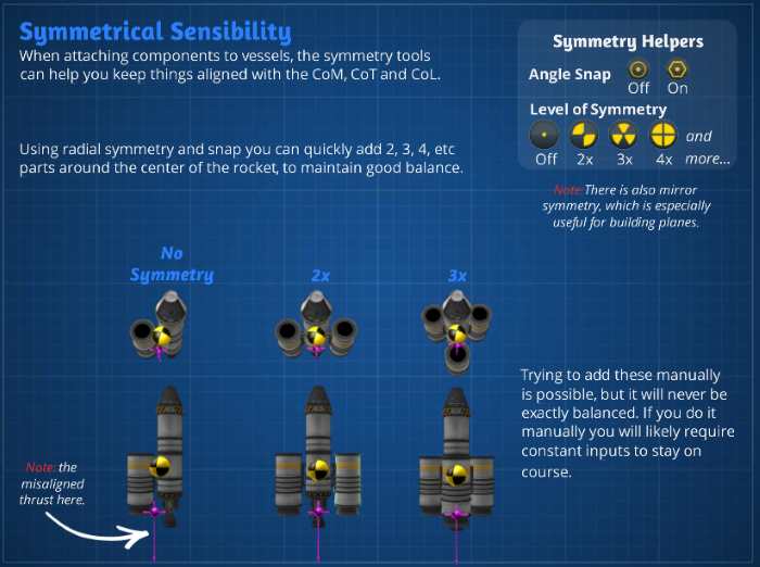
COM, COT and COL all need to be perfectly aligned along the vertical axis of the rocket.
Mass, engines and lifting surfaces all need to be placed perfectly symmetrical.
Struts and launch clamps can be used to keep the rocket rigid and reduce flex and wobble during take-off and in flight.
Active Stability
Active stability is easy; it is all about thrust. As long as COT is directly behind (pushing) or in front (pulling) of COM we have achieved active stability. It simply means not applying rotation to a rocket under thrust.
Note: Beware the Pendulum_rocket_fallacy. Push is better than pull. Apparently.
My 2 cents: as long as we have fins at the base of the rocket It Does Not Matter for flight characteristics. In real life there are other reasons why this is not practical (having to pump fuel up, heat from exhausts, parts colliding at stage separation.)
Static stability
If I throw a rocket towards you with its engines turned off (‘a dead stick’) it will either be stable in flight or not.
Examples of ‘dead sticks’ that are stable in flight:
- Badminton shuttle (pointy, tapered, perforated towards the end).
- Bullets (pointy, smooth surface, elongated, spinning).
- Arrow (pointy, elongated, feathers towards the end).
- Dart (pointy, elongated, fins in the tail)
The easiest way to improve static stability is to use fins at the base of a rocket to make sure there is more drag at the base than at the top of the rocket. Don’t add more drag than necessary to gain static stability as this will increase overall drag and reduce ΔV.
Remember:
- By placing fins at the base of a rocket, COL will move here.
- Fins at the base of a rocket generate drag, not lift.
- By placing fins in a symmetrical pattern, COL will be centered along the vertical axis of the rocket.
You can also improve stability by introducing spin; think of a spinning top or the helical grooves in a gun barrel introducing spin in the bullet. In rockets we can use inline reaction wheels to the same effect. We could try and angle the fins to mimic helical grooves in a gun barrel and make the rocket spin, but at high velocity the fins would either induce excessive spin (exposing your astronauts to high G forces) or fail to spin the sluggish mass fast enough whereby the fins would start to drag and eventually sheer off. Not a good idea.
A Service Bay can be used to store away items that would otherwise disrupt stability. Put a few lights in it if you can.
Maneuvering a rocket
There are a number of ways to maneuver a rocket. First of all you need to distinguish between maneuvering a rocket in atmosphere and maneuvering a rocket in space.
In atmosphere we can use fins. Some fins have control surfaces. By moving the control surface of some of the fins at the base of he rocket we can create lift use to maneuver the rocket whilst in atmosphere. When you jettison the first stage you jettison the fins as well.
Liquid fuel engines often can gimbal and angle their thrust vector. This works both in atmosphere and in space.
Using control thrusters in atmosphere to maneuver a rocket is not very effective;
Mono-propellant ‘Control’ or ‘Maneuvering’ thrusters are best suited for (docking) maneuvers in space. Control thrusters can be placed anywhere on the hull however locating them near the center of mass (pivot) is most common.
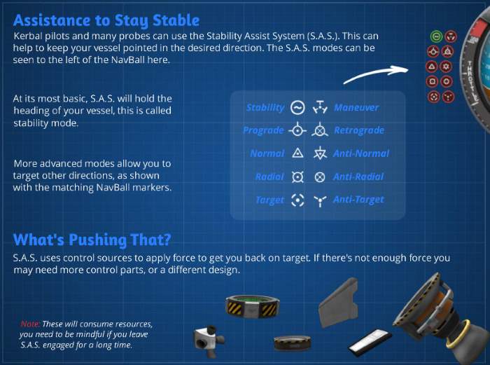
SAS acts as steering dampener by using maneuvering resources. SAS should be left enabled most of the time and is most important during launch where it helps to keep your heavy rocket pointing up.
Remember SAS will use whatever maneuvering resources are avaialble. It will use RCS if enabled and slowly drain it of mono-propellant. So only enable RCS when you really need it (take-off and docking).
Mechjeb (or KER) add-on
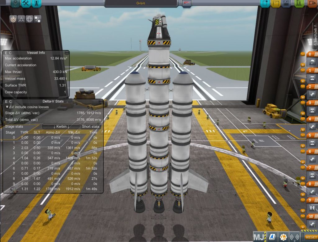
Yes, you can calculate ΔV and TWR manually, but if you change payload and components frequently, having this re-calculated instantly simply makes life easier. Not surprisingly, the solution to the problem merely changes the problem as complexity increases.
Download and install the Mechjeb add-on.
Mechjeb is an add-on that offers highly useful advanced features that can be unlocked at later stages in the Science tree. For now simply enable the “Delta-V Stats” and “Vessel Info” pop-up windows in the Vehicle Assembly Building (VAB).
Installing Add-ons
Mechjeb manual
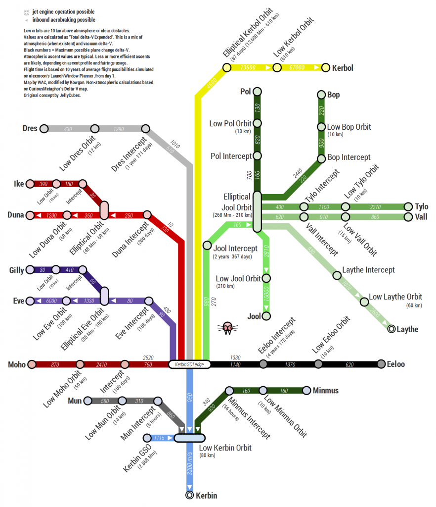
ΔV Map
Click on the picture to enlarge.
Cheat sheet
Advanced Rocketry
General Construction
(Aviation)
Flight Control
(Basic Science)
03
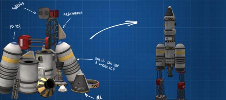
Assembly
Mk1 Command Pod
     Mk16 Parachute
     MechJeb 2 (AR-202 Case)
     Communotron 16
     Mystery Goo Containment Unit (2x)
     LT-05 Micro Landing Strut
Heat Shield (1.25m)

TR-18A Stack Decoupler
FL-T200 Fuel Tank
LV-909 "Terrier" Liquid Fuel Engine

TR-18A Stack Decoupler
FL-T400 Fuel Tank
LV-909 "Terrier" Liquid Fuel Engine

TR-18A Stack Decoupler
FL-T400 Fuel Tank
LV-909 "Terrier" Liquid Fuel Engine

TR-18A Stack Decoupler
FL-T400 Fuel Tank
LV-T30 "Reliant" Liquid Fuel Engine
|
TT-38 Radial Decoupler (2x)
FL-T400 Fuel Tank (2x4)
EAS-4 Strut Connectors (2x1)
AV-R8 Winglet (2x3)
|
Procedure
To get into Low Kerbin Orbit we need a ΔV of 3200m/s in atmosphere and a TWR of about 1.4 for the lower stage. This rocket design should only just take off. Note that we have to unlock Flight Control to obtain the MechJeb module.
Now that we have built it, it is time to learn how to get it into orbit.
