Arduino + Stepper (L298N)
Description
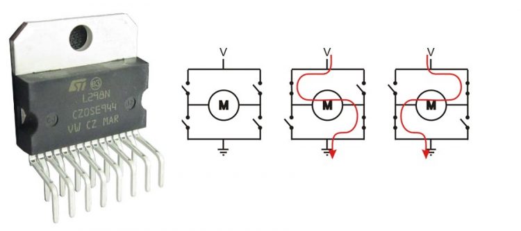
Bipolar stepper motors always have only 4 wires. Bipolar stepper motors always have 2 coils. By driving the current in seperate directions through each of the coils, we can have a total of 4 different states:
- Coil A current flowing ‘left to right’.
- Coil A current flowing ‘right to left’.
- Coil B current flowing ‘left to right’.
- Coil B current flowing ‘right to left’.
Note that the number of poles inside a stepper motor is often greater than just 2; individual physical poles inside the stepper motor are wired in series to create 2 coils / 4 wires you see in schematics.
Bipolar stepper motors require a dual H-bridge to drive them; one H-bridge for each coil. Bipolar motors offer increased torque compared to unipolar motors. Flyback diodes are required to prevent voltage spikes when the power to the coil is turned off and the stepper motor acts like a generator briefly (back-emf).
Note: You can also connect 5,6 or 8 wire unipolar motors and connect them as bipolar motors by not connecting the common lead(s). They will not have as much torque as bipolar motors due to thinner wire with a higher electrical resistance used in the coils (bifilar windings).
Hardware Required
- Arduino Board
- L298N stepper driver board
- Bipolar stepper motor (i.e. NEMA17)
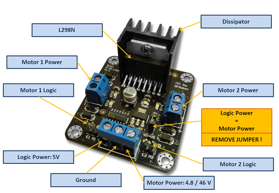
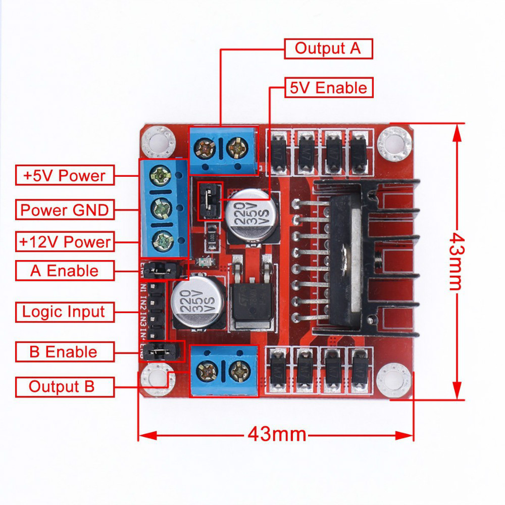
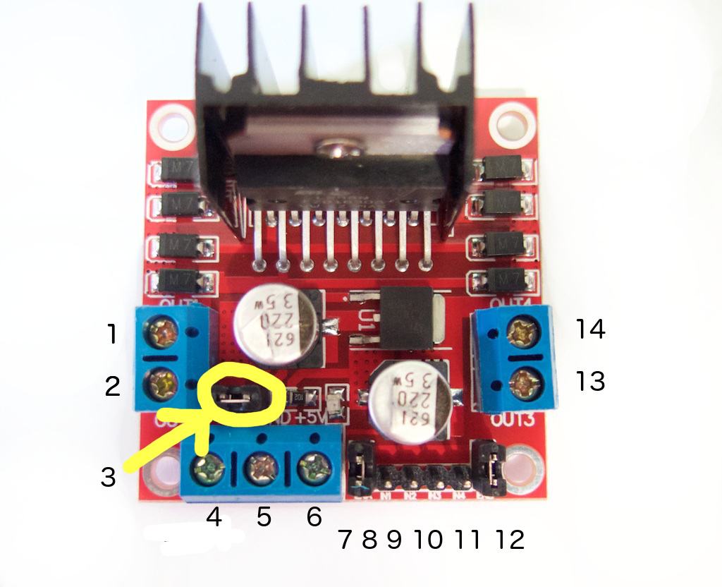
Pinout
- DC motor 1 “+” or stepper motor A+
- DC motor 1 “-” or stepper motor A-
- 12V jumper – remove this if using a supply voltage greater than 12V DC. When the jumper is in place, the onboard voltage regulator is active (12V max to 5V).
- Connect your motor supply voltage here, maximum of 35V DC. Remove 12V jumper if >12V DC
- GND
- 5V output if the 12V jumper at #3 is in place. This is ideal for powering your Arduino.
- DC motor 1 enable jumper. Leave this in place when using a stepper motor. Connect to PWM output for DC motor speed control.
- IN1
- IN2
- IN3
- IN4
- DC motor 2 enable jumper. Leave this in place when using a stepper motor. Connect to PWM output for DC motor speed control.
- DC motor 2 “+” or stepper motor B+
- DC motor 2 “-” or stepper motor B-
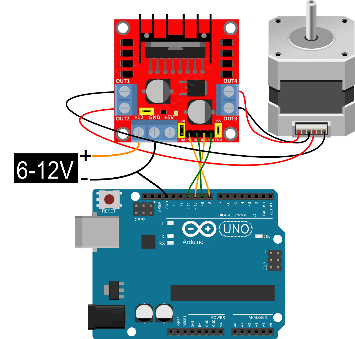
Connect the L298N stepper driver board to a 9V…12V power supply using pin #4 (+12V) and #5 (GND). Leave the jumper in #3 in place. You can now use the +5V pin at #6 (and the GND pin at #5) to power your Arduino. If you remove the jumper, the onboard voltage regulator is disabled and the +5V pin at #6 is no longer active.
Circuit
Code
Example 1
/*
 Stepper Motor Control - one revolution

 This program drives a unipolar or bipolar stepper motor.
 The motor is attached to digital pins 8 - 11 of the Arduino.

 The motor should revolve one revolution in one direction, then
 one revolution in the other direction.


 Created 11 Mar. 2007
 Modified 30 Nov. 2009
 by Tom Igoe

 */

#include <Stepper.h>

const int stepsPerRevolution = 200;  // change this to fit the number of steps per revolution
// for your motor

// initialize the stepper library on pins 8 through 11:
Stepper myStepper(stepsPerRevolution, 8, 9, 10, 11);

void setup() {
  // set the speed at 60 rpm:
  myStepper.setSpeed(60);
  // initialize the serial port:
  Serial.begin(9600);
}

void loop() {
  // step one revolution  in one direction:
  Serial.println("clockwise");
  myStepper.step(stepsPerRevolution);
  delay(500);

  // step one revolution in the other direction:
  Serial.println("counterclockwise");
  myStepper.step(-stepsPerRevolution);
  delay(500);
}
Example 2
/*
 Stepper Motor Control - one step at a time

 This program drives a unipolar or bipolar stepper motor.
 The motor is attached to digital pins 8 - 11 of the Arduino.

 The motor will step one step at a time, very slowly.  You can use this to
 test that you've got the four wires of your stepper wired to the correct
 pins. If wired correctly, all steps should be in the same direction.

 Use this also to count the number of steps per revolution of your motor,
 if you don't know it.  Then plug that number into the oneRevolution
 example to see if you got it right.

 Created 30 Nov. 2009
 by Tom Igoe

 */

#include <Stepper.h>

const int stepsPerRevolution = 200;  // change this to fit the number of steps per revolution
// for your motor

// initialize the stepper library on pins 8 through 11:
Stepper myStepper(stepsPerRevolution, 8, 9, 10, 11);

int stepCount = 0;         // number of steps the motor has taken

void setup() {
  // initialize the serial port:
  Serial.begin(9600);
}

void loop() {
  // step one step:
  myStepper.step(1);
  Serial.print("steps:");
  Serial.println(stepCount);
  stepCount++;
  delay(500);
}
Example 3
/*
 Stepper Motor Control - speed control

 This program drives a unipolar or bipolar stepper motor.
 The motor is attached to digital pins 8 - 11 of the Arduino.
 A potentiometer is connected to analog input 0.

 The motor will rotate in a clockwise direction. The higher the potentiometer value,
 the faster the motor speed. Because setSpeed() sets the delay between steps,
 you may notice the motor is less responsive to changes in the sensor value at
 low speeds.

 Created 30 Nov. 2009
 Modified 28 Oct 2010
 by Tom Igoe

 */

#include <Stepper.h>

const int stepsPerRevolution = 200;  // change this to fit the number of steps per revolution
// for your motor


// initialize the stepper library on pins 8 through 11:
Stepper myStepper(stepsPerRevolution, 8, 9, 10, 11);

int stepCount = 0;  // number of steps the motor has taken

void setup() {
  // nothing to do inside the setup
}

void loop() {
  // read the sensor value:
  int sensorReading = analogRead(A0);
  // map it to a range from 0 to 100:
  int motorSpeed = map(sensorReading, 0, 1023, 0, 100);
  // set the motor speed:
  if (motorSpeed > 0) {
    myStepper.setSpeed(motorSpeed);
    // step 1/100 of a revolution:
    myStepper.step(stepsPerRevolution / 100);
  }
}