Arduino + Serial Monitor
Description
When you upload code to an Arduino board, the computer uses serial communication to transfer the code to the device. The Arduino board contains a serial-to-USB converter chip that is detected by the computer when you first connect the Arduino board. A virtual serial port on the computer will allow the computer to send and receive data to the Arduino board.
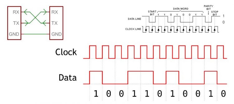
All Arduino boards have at least one serial port (also known as a UART). The serial port communicates on digital pins 0 (RX) and 1 (TX) and feeds into the serial-to-USB converter chip to the computer. If you program the Arduino using serial communication (over USB) you will see the TX and RX LEDs flicker rapidly to indicate activity.
You can use the Arduino environment’s built-in serial monitor to communicate with an Arduino board. Click the serial monitor button in the toolbar and select the same baud rate as used in your code. Again, you will see the TX and RX LEDs flicker briefly when you send data using serial communication.
You can also use a serial port to have your Arduino board communicate over serial to another integrated circuit (chip) or logic board.
It is good practice not to use pins 0 and 1 as digital input or output if you can avoid it as this will make it impossible to communicate with the Arduino board when your code is running.
Some Arduino boards have multiple serial ports. Arduino board can also communicate using I2C or SPI communication protocols.
Serial communication
The most basic serial protocol uses a single DATA wire (and GND). This is known as asynchronous serial communication. Synchronous communication uses a DATA and CLOCK wire (and GND) to send information. The receiver locks-in data bits on the DATA wire only on the rising (or falling) edge of the clock pulse on the CLOCK wire. The CLOCK signal acts as a metronome (*tick-tock-tick-tock*) to help the receiver determine when to lock-in data on the DATA wire.
RS232 serial communication uses a 9-pin serial connector and can reach +12V voltage levels. It is used for longer distance serial communication. Early systems only allowed for half-duplex (one direction at a time) connections. Additional pins perform handshaking to help determine which side is allowed to talk. RS232 has largely been replaced by serial-over-USB.
Serial communication does not perform error control nor does it re-transmit data.
Hardware required
- Arduino board
Circuit
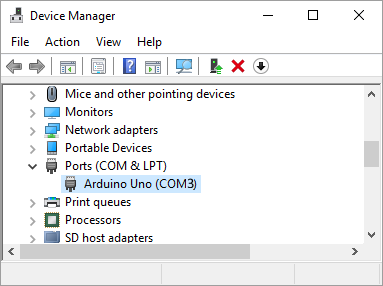
No circuit required. Simply connect the Arduino board to the computer with a USB cable. If you have installed the Arduino software, you should now have a COM (serial) port in Device Manager.
Code
void setup() {

    // Open serial port using 9600 baudrate
    Serial.begin(9600);

 }

 void loop() {

    // Send data over serial
    Serial.println("Hello World!");

}
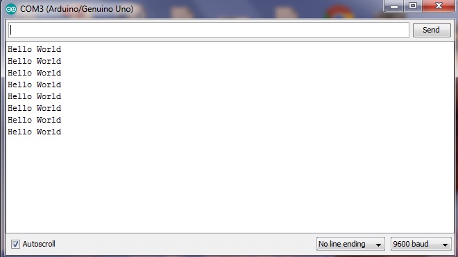
If you have selected the correct Arduino board (i.e. Arduino Uno) and port number (i.e. COM3), you will be able to open the Serial Monitor utility, select the correct baudrate and see the following text:
Examples:
- Serial.print(78, BIN) gives “1001110”
- Serial.print(78, OCT) gives “116”
- Serial.print(78, DEC) gives “78”
- Serial.print(78, HEX) gives “4E”
- Serial.print(\t) gives a TAB character
- Serial.print(\r) gives a CR (CARRIAGE RETURN) character (ASCII 13)
- Serial.print(\n) gives a (LF) LINE FEED -also known as (N) NEWLINE- character (ASCII 10)
To start a new line you would use
Serial.println("Hello World");
or
Serial.print("Hello World\r\n");