
Arduino + LEDs
Description
Blinking a single LED is not all that hard. But how do we go from there to driving 8 LEDs connected to an Arduino board?
Hardware Required
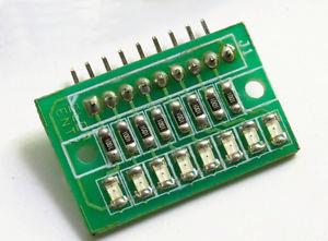
There are a large number of similar boards on the market. They either have a common ground or common Vcc pin (active low logic). The exact pinout may vary, but in its most basic form it would look something like this:
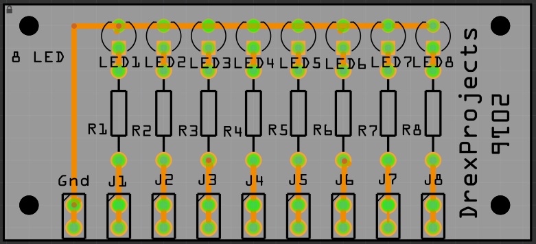
Pinout
- GND – Ground
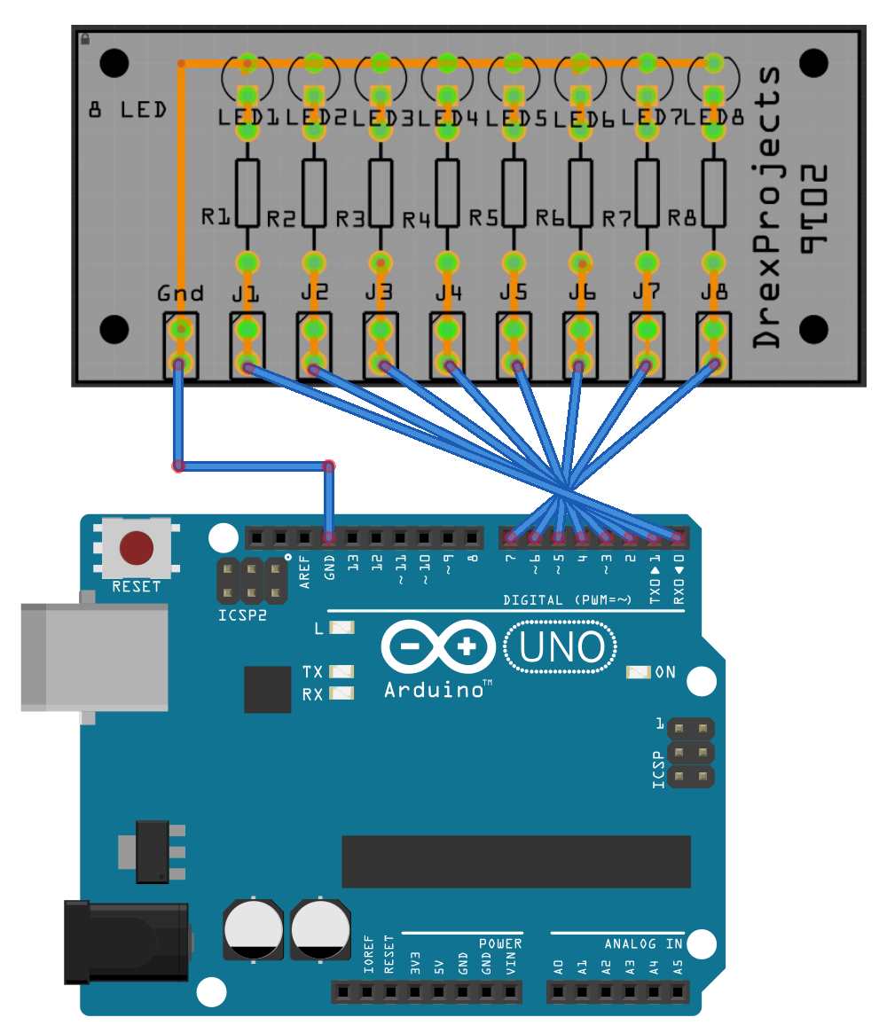
- J1…J8 – Input (active high)
Schematic
Code
Let’s create a running light that moves from left to right and back again in 10 steps with a delay of 500msec in between steps. If you grew up with Battlestar Galactica (cylons) or Knight Rider I should not have to explain…
Example 1 – Running light using plain coding
const int LED1 = 0;  //warning: RX pin.
const int LED2 = 1;  //warning: TX pin.
const int LED3 = 2;
const int LED4 = 3;
const int LED5 = 4;
const int LED6 = 5;
const int LED7 = 6;
const int LED8 = 7;

void setup() {
  // put your setup code here, to run once:

  pinMode(LED1, OUTPUT);
  pinMode(LED2, OUTPUT);
  pinMode(LED3, OUTPUT);
  pinMode(LED4, OUTPUT);
  pinMode(LED5, OUTPUT);
  pinMode(LED6, OUTPUT);
  pinMode(LED7, OUTPUT);
  pinMode(LED8, OUTPUT);

}

void loop() {
  // put your main code here, to run repeatedly:

  digitalWrite(LED1, HIGH);
  delay(500);

  digitalWrite(LED1, LOW);
  digitalWrite(LED2, HIGH);
  delay(500);

  digitalWrite(LED2, LOW);
  digitalWrite(LED3, HIGH);
  delay(500);

  digitalWrite(LED3, LOW);
  digitalWrite(LED4, HIGH);
  delay(500);

  digitalWrite(LED4, LOW);
  digitalWrite(LED5, HIGH);
  delay(500);

  digitalWrite(LED5, LOW);
  digitalWrite(LED6, HIGH);
  delay(500);

  digitalWrite(LED6, LOW);
  digitalWrite(LED7, HIGH);
  delay(500);

  digitalWrite(LED7, LOW);
  digitalWrite(LED8, HIGH);
  delay(500);

  digitalWrite(LED8, LOW);
  delay(500);

  digitalWrite(LED8, HIGH);
  delay(500);

  digitalWrite(LED8, LOW);
  digitalWrite(LED7, HIGH);
  delay(500);

  digitalWrite(LED7, LOW);
  digitalWrite(LED6, HIGH);
  delay(500);

  digitalWrite(LED6, LOW);
  digitalWrite(LED5, HIGH);
  delay(500);

  digitalWrite(LED5, LOW);
  digitalWrite(LED4, HIGH);
  delay(500);

  digitalWrite(LED4, LOW);
  digitalWrite(LED3, HIGH);
  delay(500);

  digitalWrite(LED3, LOW);
  digitalWrite(LED2, HIGH);
  delay(500);

  digitalWrite(LED2, LOW);
  digitalWrite(LED1, HIGH);
  delay(500);

  digitalWrite(LED1, LOW);
  delay(500);

}
Example 2 – Running light using a “for” loop
Arduino supports loops. When you do the same thing over and over again, it may be a good idea to consider using a “for” loop.
There are three parts to the for loop:
for (initialization; condition; increment) {//statement(s);}
The following example will print the numbers 0 to 9:
for (i=0;i<10;i++) {
  Serial.println(i);
}
The following code does more or less the same as the code in Example 1, but is far more compact.
int count = 0;
int timer = 500;

void setup() {
  // put your setup code here, to run once:

  for (count=0;count<8;count++) {
    pinMode(count, OUTPUT);
  }
}

void loop() {
  // put your main code here, to run repeatedly:

   for (count=0;count<8;count++) {
   digitalWrite(count, HIGH);
   delay(timer);
   digitalWrite(count, LOW);
   delay(timer);
  }

  for (count=7;count>=0;count--) {
   digitalWrite(count, HIGH);
   delay(timer);
   digitalWrite(count, LOW);
   delay(timer);
  }

}
But what if we have a light sequence where multiple LEDs need to be turned on or off?
Suppose we want to create the following ‘spaceship docking port sort of’ lights pattern:
| Step 1 | X | X | ||||||
| Step 2 | X | X | ||||||
| Step 3 | X | X | ||||||
| Step 4 | X | X | ||||||
| Step 5 | ||||||||
| Step 6 | X | X | ||||||
| Step 7 | X | X | ||||||
| Step 8 | X | X | ||||||
| Step 9 | X | X | ||||||
| Step 10 |
Example 3 – Double running light using plain coding
const int LED1 = 0;  //warning: RX pin.
const int LED2 = 1;  //warning: TX pin.
const int LED3 = 2;
const int LED4 = 3;
const int LED5 = 4;
const int LED6 = 5;
const int LED7 = 6;
const int LED8 = 7;

void setup() {
  // put your setup code here, to run once:

  pinMode(LED1, OUTPUT);
  pinMode(LED2, OUTPUT);
  pinMode(LED3, OUTPUT);
  pinMode(LED4, OUTPUT);
  pinMode(LED5, OUTPUT);
  pinMode(LED6, OUTPUT);
  pinMode(LED7, OUTPUT);
  pinMode(LED8, OUTPUT);

}

void loop() {
  // put your main code here, to run repeatedly:

  //step 1
  digitalWrite(LED1, HIGH);
  digitalWrite(LED2, LOW);
  digitalWrite(LED3, LOW);
  digitalWrite(LED4, LOW);
  digitalWrite(LED5, LOW);
  digitalWrite(LED6, LOW);
  digitalWrite(LED7, LOW);
  digitalWrite(LED8, HIGH);
  delay (500);

  //step 2
  digitalWrite(LED1, LOW);
  digitalWrite(LED2, HIGH);
  digitalWrite(LED3, LOW);
  digitalWrite(LED4, LOW);
  digitalWrite(LED5, LOW);
  digitalWrite(LED6, LOW);
  digitalWrite(LED7, HIGH);
  digitalWrite(LED8, LOW);
  delay (500);

  //step 3
  digitalWrite(LED1, LOW);
  digitalWrite(LED2, LOW);
  digitalWrite(LED3, HIGH);
  digitalWrite(LED4, LOW);
  digitalWrite(LED5, LOW);
  digitalWrite(LED6, HIGH);
  digitalWrite(LED7, LOW);
  digitalWrite(LED8, LOW);
  delay (500);

  //step 4
  digitalWrite(LED1, LOW);
  digitalWrite(LED2, LOW);
  digitalWrite(LED3, LOW);
  digitalWrite(LED4, HIGH);
  digitalWrite(LED5, HIGH);
  digitalWrite(LED6, LOW);
  digitalWrite(LED7, LOW);
  digitalWrite(LED8, LOW);
  delay (500);

  //step 5
  digitalWrite(LED1, LOW);
  digitalWrite(LED2, LOW);
  digitalWrite(LED3, LOW);
  digitalWrite(LED4, LOW);
  digitalWrite(LED5, LOW);
  digitalWrite(LED6, LOW);
  digitalWrite(LED7, LOW);
  digitalWrite(LED8, LOW);
  delay (500);

  //step 6
  digitalWrite(LED1, LOW);
  digitalWrite(LED2, LOW);
  digitalWrite(LED3, LOW);
  digitalWrite(LED4, HIGH);
  digitalWrite(LED5, HIGH);
  digitalWrite(LED6, LOW);
  digitalWrite(LED7, LOW);
  digitalWrite(LED8, LOW);
  delay (500);

  //step 7
  digitalWrite(LED1, LOW);
  digitalWrite(LED2, LOW);
  digitalWrite(LED3, HIGH);
  digitalWrite(LED4, LOW);
  digitalWrite(LED5, LOW);
  digitalWrite(LED6, HIGH);
  digitalWrite(LED7, LOW);
  digitalWrite(LED8, LOW);
  delay (500);

   //step 8
  digitalWrite(LED1, LOW);
  digitalWrite(LED2, HIGH);
  digitalWrite(LED3, LOW);
  digitalWrite(LED4, LOW);
  digitalWrite(LED5, LOW);
  digitalWrite(LED6, LOW);
  digitalWrite(LED7, HIGH);
  digitalWrite(LED8, LOW);
  delay (500);

  //step 9
  digitalWrite(LED1, HIGH);
  digitalWrite(LED2, LOW);
  digitalWrite(LED3, LOW);
  digitalWrite(LED4, LOW);
  digitalWrite(LED5, LOW);
  digitalWrite(LED6, LOW);
  digitalWrite(LED7, LOW);
  digitalWrite(LED8, HIGH);
  delay (500);

  //step 10
  digitalWrite(LED1, LOW);
  digitalWrite(LED2, LOW);
  digitalWrite(LED3, LOW);
  digitalWrite(LED4, LOW);
  digitalWrite(LED5, LOW);
  digitalWrite(LED6, LOW);
  digitalWrite(LED7, LOW);
  digitalWrite(LED8, LOW);
  delay (500);

}
We cannot use loops the same way we did previously to simplify this code. However, we can use something called “port registers”.
Port Registers
Port registers allow for lower-level and faster manipulation of the I/O pins. Most Arduino boards recognize the following port registers:
- Port B (digital pin 8 to 13)
- Port C (analog input pins)
- Port D (digital pins 0 to 7)
Each port is controlled by three registers:
- DDR register – determines whether the pin is an INPUT or OUTPUT.
- PORT register – writes to the ports (if configured as OUTPUT).
- PIN register – reads the state of the port (if configured as INPUT).
DDR and PORT registers may be both written to, and read. PIN registers correspond to the state of inputs and may only be read.
PORTD maps to Arduino digital pins 0 to 7
-
DDRD – The Port D Data Direction Register – read/writePORTD – The Port D Data Register – read/writePIND – The Port D Input Pins Register – read only
PORTB maps to Arduino digital pins 8 to 13 The two high bits (6 & 7) map to the crystal pins and are not usable
-
DDRB – The Port B Data Direction Register – read/writePORTB – The Port B Data Register – read/writePINB – The Port B Input Pins Register – read only
PORTC maps to Arduino analog pins 0 to 5. Pins 6 & 7 are only accessible on the Arduino Mini
-
DDRC – The Port C Data Direction Register – read/writePORTC – The Port C Data Register – read/writePINC – The Port C Input Pins Register – read only
Let’s have a closer look at PortD registers that control Arduino digital pins 0 to 7 (what a coincidence; this matches perfectly with our circuit!)
DDRD is the direction register for Port D (Arduino digital pins 0-7). The bits in this register control whether the pins in PORTD are configured as inputs or outputs so, for example:
DDRD = B11111110;  // configure pins 0 to 7 as OUTPUT
PORTD = B11000011; // make pin0, pin1, pin6 and pin7 HIGH, pin2..pin5 LOW
Generally speaking, doing this sort of thing is not a good idea. Why not? Here are a few reasons:
- The code is much more difficult for you to debug and maintain, and is a lot harder for other people to understand. It only takes a few microseconds for the processor to execute code, but it might take hours for you to figure out why it isn’t working right and fix it! Your time is valuable, right? But the computer’s time is very cheap, measured in the cost of the electricity you feed it. Usually it is much better to write code the most obvious way.
- The code is less portable. If you use digitalRead() and digitalWrite(), it is much easier to write code that will run on all of the Atmel microcontrollers, whereas the control and port registers can be different on each kind of microcontroller.
- It is a lot easier to cause unintentional malfunctions with direct port access. Notice how the line DDRD = B11111110; above mentions that it must leave pin 0 as an input pin. Pin 0 is the receive line (RX) on the serial port. It would be very easy to accidentally cause your serial port to stop working by changing pin 0 into an output pin! Now that would be very confusing when you suddenly are unable to receive serial data, wouldn’t it?
So you might be saying to yourself, great, why would I ever want to use this stuff then? Here are some of the positive aspects of direct port access:
- You may need to be able to turn pins on and off very quickly, meaning within fractions of a microsecond. If you look at the source code in lib/targets/arduino/wiring.c, you will see that digitalRead() and digitalWrite() are each about a dozen or so lines of code, which get compiled into quite a few machine instructions. Each machine instruction requires one clock cycle at 16MHz, which can add up in time-sensitive applications. Direct port access can do the same job in a lot fewer clock cycles.
- Sometimes you might need to set multiple output pins at exactly the same time. Calling digitalWrite(10,HIGH); followed by digitalWrite(11,HIGH); will cause pin 10 to go HIGH several microseconds before pin 11, which may confuse certain time-sensitive external digital circuits you have hooked up. Alternatively, you could set both pins high at exactly the same moment in time using PORTB |= B1100;
- If you are running low on program memory, you can use these tricks to make your code smaller. It requires a lot fewer bytes of compiled code to simultaneously write a bunch of hardware pins simultaneously via the port registers than it would using a for loop to set each pin separately. In some cases, this might make the difference between your program fitting in flash memory or not!
Now that we know all this, let’s see if we can use this to improve our double running lights sequence:
Example 4 – Double running light using Port Registers
int timer = 500;

void setup() {
  // put your setup code here, to run once:

  DDRD = B11111111;  // configure pins 0 to 7 as OUTPUT

}

void loop() {
  // put your main code here, to run repeatedly:

  PORTD=B10000001;
  delay(timer);
  PORTD=B01000010;
  delay(timer);
  PORTD=B00100100;
  delay(timer);
  PORTD=B00011000;
  delay(timer);
  PORTD=B00000000;
  delay(timer);
  PORTD=B00011000;
  delay(timer);
  PORTD=B00100100;
  delay(timer);
  PORTD=B01000010;
  delay(timer);
  PORTD=B10000001;
  delay(timer);
  PORTD=B00000000;
  delay(timer);

}
Here are some additional Knight Rider based code examples from the corners of the internet. Note these examples use only 6 LED lights. This leaves the TX and RX pin of the Arduino available for serial communication.
Knight Rider 1
/* Knight Rider 1
 * --------------
 *
 * Basically an extension of Blink_LED.
 *
 *
 * (cleft) 2005 K3, Malmo University
 * @author: David Cuartielles
 * @hardware: David Cuartielles, Aaron Hallborg
 */

int pin2 = 2;
int pin3 = 3;
int pin4 = 4;
int pin5 = 5;
int pin6 = 6;
int pin7 = 7;
int timer = 100;

void setup(){
  pinMode(pin2, OUTPUT);
  pinMode(pin3, OUTPUT);
  pinMode(pin4, OUTPUT);
  pinMode(pin5, OUTPUT);
  pinMode(pin6, OUTPUT);
  pinMode(pin7, OUTPUT);
}

void loop() {
   digitalWrite(pin2, HIGH);
   delay(timer);
   digitalWrite(pin2, LOW);
   delay(timer);

   digitalWrite(pin3, HIGH);
   delay(timer);
   digitalWrite(pin3, LOW);
   delay(timer);

   digitalWrite(pin4, HIGH);
   delay(timer);
   digitalWrite(pin4, LOW);
   delay(timer);

   digitalWrite(pin5, HIGH);
   delay(timer);
   digitalWrite(pin5, LOW);
   delay(timer);

   digitalWrite(pin6, HIGH);
   delay(timer);
   digitalWrite(pin6, LOW);
   delay(timer);

   digitalWrite(pin7, HIGH);
   delay(timer);
   digitalWrite(pin7, LOW);
   delay(timer);

   digitalWrite(pin6, HIGH);
   delay(timer);
   digitalWrite(pin6, LOW);
   delay(timer);

   digitalWrite(pin5, HIGH);
   delay(timer);
   digitalWrite(pin5, LOW);
   delay(timer);

   digitalWrite(pin4, HIGH);
   delay(timer);
   digitalWrite(pin4, LOW);
   delay(timer);

   digitalWrite(pin3, HIGH);
   delay(timer);
   digitalWrite(pin3, LOW);
   delay(timer);
}
Knight Rider 2
Arduino supports “Arrays”. An array is a collection of values that are accessed with an index number. Arrays are zero indexed, that is, referring to the array initialization above, the first element of the array is at index 0.
Suppose we have the following array:
int pinArray[] = {2, 3, 4, 5, 6, 7};
We can query the elements in the array using the desired index number.
Serial.println(pinArray(0))    returns the value 2 (= first element of the array)
Serial.println(pinArray(1))    returns the value 3 (= second element of the array)
Serial.println(pinArray(2))    returns the value 4 (= third element of the array)
Arrays are often used in combination with “for” loops to iterate the individual elements of an array.
/* Knight Rider 2
 * --------------
 *
 * Reducing the amount of code using for(;;).
 *
 *
 * (cleft) 2005 K3, Malmo University
 * @author: David Cuartielles
 * @hardware: David Cuartielles, Aaron Hallborg
 */

int pinArray[] = {2, 3, 4, 5, 6, 7};
int count = 0;
int timer = 100;

void setup(){
  // we make all the declarations at once
  for (count=0;count<6;count++) {
    pinMode(pinArray[count], OUTPUT);
  }
}

void loop() {
  for (count=0;count<6;count++) {
   digitalWrite(pinArray[count], HIGH);
   delay(timer);
   digitalWrite(pinArray[count], LOW);
   delay(timer);
  }
  for (count=5;count>=0;count--) {
   digitalWrite(pinArray[count], HIGH);
   delay(timer);
   digitalWrite(pinArray[count], LOW);
   delay(timer);
  }
}
Knight Rider 3
/* Knight Rider 3
 * --------------
 *
 * This example concentrates on making the visuals fluid.
 *
 *
 * (cleft) 2005 K3, Malmo University
 * @author: David Cuartielles
 * @hardware: David Cuartielles, Aaron Hallborg
 */

int pinArray[] = {2, 3, 4, 5, 6, 7};
int count = 0;
int timer = 30;

void setup(){
  for (count=0;count<6;count++) {
    pinMode(pinArray[count], OUTPUT);
  }
}

void loop() {
  for (count=0;count<5;count++) {
   digitalWrite(pinArray[count], HIGH);
   delay(timer);
   digitalWrite(pinArray[count + 1], HIGH);
   delay(timer);
   digitalWrite(pinArray[count], LOW);
   delay(timer*2);
  }
  for (count=5;count>0;count--) {
   digitalWrite(pinArray[count], HIGH);
   delay(timer);
   digitalWrite(pinArray[count - 1], HIGH);
   delay(timer);
   digitalWrite(pinArray[count], LOW);
   delay(timer*2);
  }
}