Arduino + Serial (ASCII)
Microcontrollers operate on +3.3Vdc or +5Vdc relative to GND typically. Digital electronics consider a signal of +5Vdc (or +3.3Vdc) HIGH and a signal of 0Vdc LOW. Arduino microcontrollers treat voltages on a digital I/O pin above +0.7Vdc as HIGH and voltages below +0.3Vdc as LOW. If a digital I/O pin is not connected, electrostatic discharge and hysteresis often cause pin voltage levels to fluctuate between HIGH and LOW. A pin that is not connected is called a floating pin. If your circuit is behaving erratically you should check for floating pins and consider connecting to power, ground or signal.
Ones and zeros
Most often a HIGH signal represents a logical one (1) and a LOW signal represents a logical zero (0) in software code.
Active-low logic
For inverse logic or ‘active-low’ logic a pin is considered logical zero (0) when HIGH and logical one (1) when LOW. This may sound counter intuitive at first but this makes sense for use in safety critical applications where action can be taken if a circuit does not maintain a constant +5Vdc signal when at rest, indicating a possible hardware failure or power failure.
So if a microcontroller only understands “one” and “zero”, how can we send numbers?
Counting in binary
When we count in decimal notation, we have the symbols 0, 1, 2, 3, 4, 5, 6, 7, 8, 9 at our disposal. You could say we have 10 different voltage levels our electronics can differentiate between. Just imagine how susceptible this would be to noise and voltage ripple. Either way, when we want to write down the number twelve in decimal notation for example, we do as follows:
Decimal
0000 zero
0001 one
0002 two
0003 three
0004 four
0005 five
0006 six
0007 seven
0008 eight
0009 nine
0010 ten  <-- Notice the 'carry over' to the next digit.
0011 eleven
0012 twelve
...
This should not come as a surprise. So how would you count to twelve in binary, where we only have 2 symbols / voltage levels at our disposal rather than 10? Well, like so:
Binary
0000 zero
0001 one
0010 two  <-- Notice the 'carry over' to the next digit.
0011 three
0100 four  <-- another 'carry over'
0101 five
0110 six  <-- and another 'carry over'
0111 seven
1000 eight  <-- and another 'carry over'
1001 nine
1010 ten  <-- and another 'carry over'
1011 eleven
1100 twelve  <-- and another 'carry over'
As you can see we can count as high as we want; it just means that are number will simply be ‘longer’ than if you were to use decimal notation.
So if a microcontroller only understands “ones” and “zeros” and we have learned how to count numbers with only 2 symbols, how can we send text ?
ASCII table
Regardless of whether you have ’10 voltage levels’ like with counting in decimal or ‘2 voltage levels’ like counting in binary, you will have to come up with some sort of lookup table because we simply have many more text characters than we have symbols for.
This lookup table is called the ASCII table.
| Letter | ASCII Code (Decimal) | ASCII Code (Binary) | Letter | ASCII Code (Decimal) | ASCII Code (Binary) |
|---|---|---|---|---|---|
| a | 097 | 01100001 | A | 065 | 01000001 |
| b | 098 | 01100010 | B | 066 | 01000010 |
| c | 099 | 01100011 | C | 067 | 01000011 |
| d | 100 | 01100100 | D | 068 | 01000100 |
| e | 101 | 01100101 | E | 069 | 01000101 |
| f | 102 | 01100110 | F | 070 | 01000110 |
| g | 103 | 01100111 | G | 071 | 01000111 |
| h | 104 | 01101000 | H | 072 | 01001000 |
| i | 105 | 01101001 | I | 073 | 01001001 |
| j | 106 | 01101010 | J | 074 | 01001010 |
| k | 107 | 01101011 | K | 075 | 01001011 |
| l | 108 | 01101100 | L | 076 | 01001100 |
| m | 109 | 01101101 | M | 077 | 01001101 |
| n | 110 | 01101110 | N | 078 | 01001110 |
| o | 111 | 01101111 | O | 079 | 01001111 |
| p | 112 | 01110000 | P | 080 | 01010000 |
| q | 113 | 01110001 | Q | 081 | 01010001 |
| r | 114 | 01110010 | R | 082 | 01010010 |
| s | 115 | 01110011 | S | 083 | 01010011 |
| t | 116 | 01110100 | T | 084 | 01010100 |
| u | 117 | 01110101 | U | 085 | 01010101 |
| v | 118 | 01110110 | V | 086 | 01010110 |
| w | 119 | 01110111 | W | 087 | 01010111 |
| x | 120 | 01111000 | X | 088 | 01011000 |
| y | 121 | 01111001 | Y | 089 | 01011001 |
| z | 122 | 01111010 | Z | 090 | 01011010 |
Note: This is only a subset of the ASCII table; the complete ASCII table contains many more characters including special characters, punctuation marks, numbers, symbols and basic shapes.
Experiment
Open a text editor program (i.e. ‘Notepad’) on your computer and keep the [ALT] key pressed down. Then, with the [ALT] key pressed down, enter the numbers [0], [9], [7] or just [9], [7] and you will see the letter ‘a’ appear on the screen. You can experiment and see what other codes do if you like.
Serial communication
An Arduino microcontroller is programmed using serial communication. We can also use the Arduino microcontroller to send information back to the computer using serial communication.
Arduino serial communication by default uses a 9600 8n1 pattern:
- Speed = 9600 baud (= bits per second)
- Data packet = 8 bits
- No parity
- 1 stop bit
The serial TX line is +5Vdc when idle. First, a start bit is sent where the voltage level drops from +5Vdc to 0Vdc. This triggers the receiver to start latching data at specific intervals. Next, a data packet of 8 data bits is sent. The receiver will latch the data. Then, a stop bit is sent where the TX line goes back to idle (+5Vdc).
So let’s put this to the test.
Hardware Required
- Arduino Board
- Oscilloscope
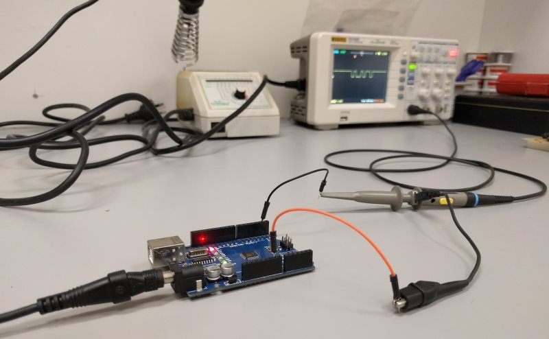
Circuit
- Connect the oscilloscope measuring probe to the TX pin (pin 1) of the Arduino and the probe ground clip to GND.
Code
void setup() {
    Serial.begin(9600);
 }

 void loop() {
    Serial.print("i");
    delay(100);
}
Oscilloscope
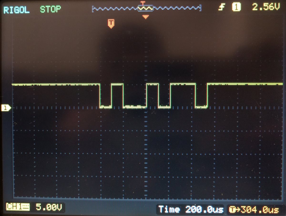
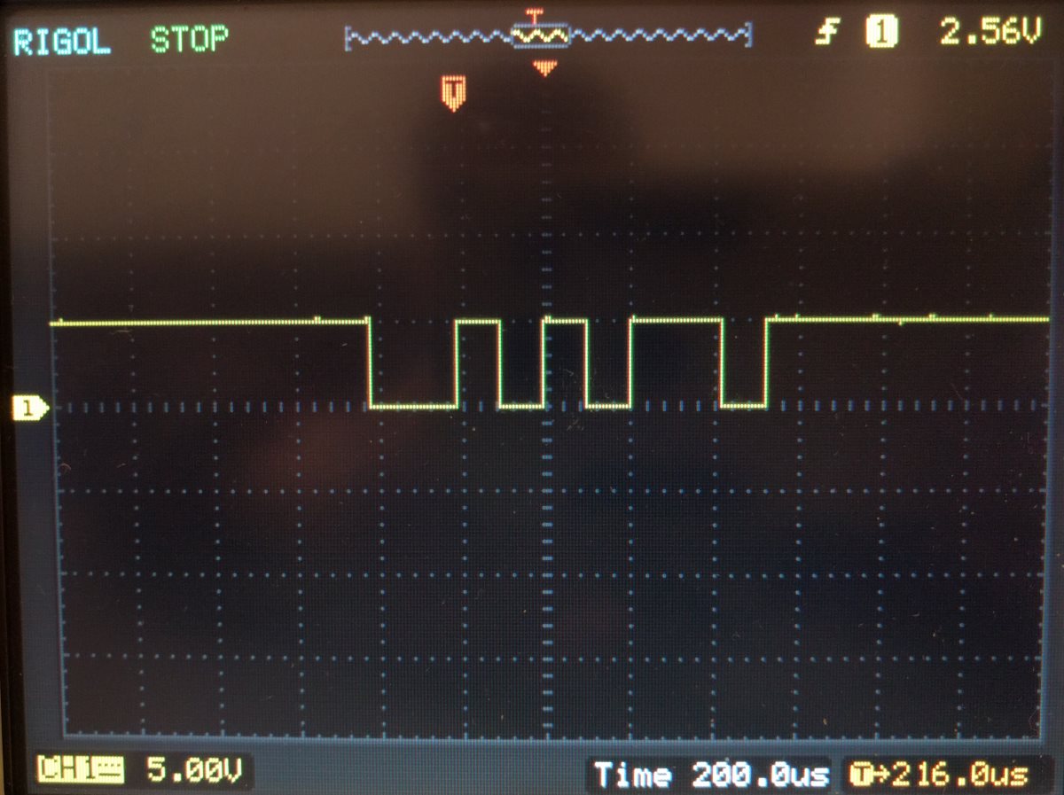
The binary ASCII code for the symbol “i” is “01101001”. Note the following oscilloscope image:
How to read an oscilloscope
The vertical axis (voltage) scale is set to 5Vdc per division. We can recognize individual ‘ones’ (+5Vdc) and ‘zeros’ (0Vdc) in the pulse train pattern. The horizontal axis (time base) scale is set to 200 microseconds per division. A period of 200 microseconds equals 5000Hz. We can see the individual bits take up roughly half a division or 100 microseconds. 100 microseconds translates to 10.000Hz or 10.000 bits per second, which is close to our 9600 bits per second or 9600 baud. You can see the pulse train does not perfectly fit the grid as a result of this slight mismatch.
An oscilloscope starts to plot a signal on the screen from left to right. If you were to set the time base scale to 0.2s per division you would actually see the signal being drawn on the display. When the oscilloscope detects a signal repeating itself (triggering), it will overwrite the contents on the screen.
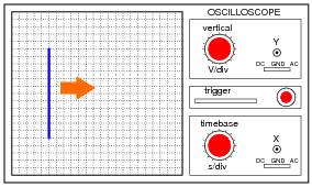
This means the samples on the left hand side of the screen are the ‘oldest’. So to find the bits that were sent first, we have to start reading from left to right.
Edge triggering
Rather than counting the ‘highs’ and ‘lows’ in a bit pattern on an oscilloscope, it often makes more sense to focus on the flanks or edges of a signal rather than dips or peaks. Electronics often use edge triggering to latch values. So when a signal changes from high to low it would count as a logical zero and when a signal changes from low to high it would count as a logical one. It is these transitions that represent a bit value, not so much the ‘low’ or ‘high’ dips and peaks. You will be able to recognize the start and stop bits more easily if you train your eye on recognizing the rising edge or falling edge as the center of each bit.
So back to the oscilloscope image:
The far left hand side begins with a high-to-low transition; the start bit.
Followed by a low-to-high transition; a logical one.
Followed by a high-to-low transition; a logical zero.
Then nothing happens; a logical zero.
Then a low-to-high transition; a logical one.
Then a zero.
Then two ones.
Then a zero.
As this makes a total of 8, the remaining transition from low-to-high must be the stop bit to signal the end of the transmission.
Most significant bit (MSB) versus Least significant bit (LSB)
In a binary number value, the most significant bit -the digit of the number that carries the most ‘weight’- would be the digit on the far left. The least significant bit – the digits that carries the least ‘weight’- would be the digit on the far right. The least significant bit in the binary number below represents a value of just 1 where the most significant bit in the 8 digit number below represents a value of 128.
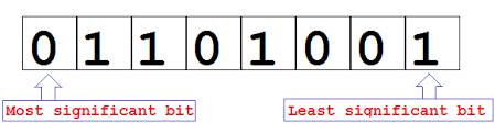
It appears the ‘least significant bit’ of our character “i” binary code sequence was sent first, so we would write down the number sequence from right to left as in the above picture.
The binary ASCII code for the symbol “i” is “01101001”, which is a match with our signal.
This is how a character “i” is transmitted over the wire when sent from an Arduino microcontroller to a computer.
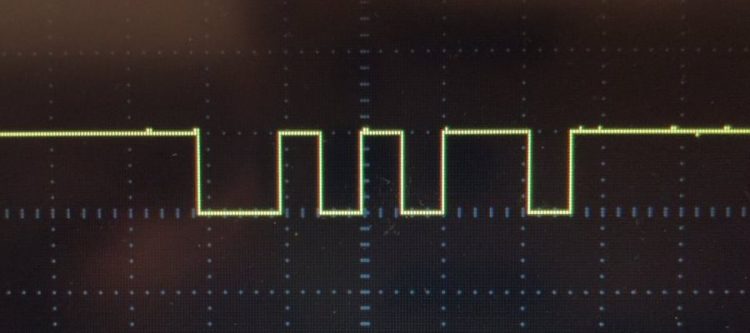
If we repeat the experiment and instead send the character “j” we receive the following sequence:
The far left hand side shows a high-to-low transition; the start bit.
Followed by a zero.
Then a one.
Then a zero.
Then a one.
Then a zero.
Then two ones.
Then a zero.
As this makes a total of 8, the remaining low-to-high transition must be the stop bit to signal the end of the transmission.
The binary ASCII code for the symbol “j” is “01101010”, which is a match with our signal.