Arduino – DC Motor
Description
Alternating Current (AC) and Direct Current (DC) are fundamentally different.
Alternating Current (AC)
Mains power in Australia uses 240Vac 50Hz sine wave alternating current. One of the benefits of alternating current is that it can be transported over long distances using high voltage transmission lines with minimal power loss compared to direct current. Alternating current is generated by three phase power generators. The average residential home is connected to single phase mains power.
Direct Current (DC)
Direct Current (DC) is mostly used in batteries (lead-acid, NiMh, Li-Ion, LiPo) and comes in many form factors (1.5V AA / AAA, 9V battery, 18650, cell phone battery pack, power tools batteries, car battery, etc.). Direct current can also be generated by rectifying or switching alternating current, either by using a step down transformer with diode bridge rectifier and ripple smoothing capacitor or by using a switching transformer.
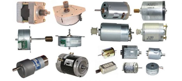
DC motor
DC motor (brushed)
The DC motor in its simplest form uses a permanent magnet stator and an electrical coil rotor. A mechanical commutator is used to alternate the magnetic field (N-S to S-N and vice versa). By adding additional coils and increasing the number of poles on the commutator operation is improved.
DC motor (brushless)
Brushless DC motors use multiple coils driven in sequence not dissimilar to stepper motors. A hall effect sensor is used to measure the orientation of the permanent magnet rotor magnetic field to help determine which coil to energize.
DC motor (outrunner)
The term outrunner refers to a type of brushless motor primarily used in radio-controlled model aircraft. This type of motor spins its outer shell around its windings, much like motors found in ordinary CD-ROM computer drives. Usually, outrunners have more poles than their inrunner counterparts and spin slower but produce more more torque. This makes an outrunner an excellent choice for directly driving electric aircraft propellers since they eliminate the extra weight, complexity, inefficiency and noise of a gearbox.
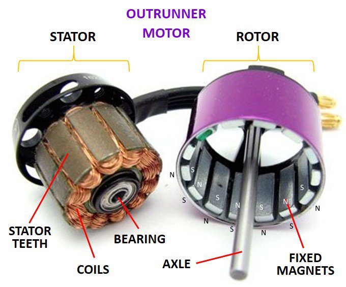
Outrunner motors have quickly become popular and are now available in many sizes. They have also become popular in personal, electric transportation applications such as electric bikes and scooters due to their compact size and high efficiency.
Driving a DC motor
An Arduino can operate on 5Vdc directly from a USB port, or on input voltages of 7V…12Vdc when using the DC plug connector which is connected to the on-board 5V voltage regulator. If your DC motor requires 12Vdc or less, you can use the same power supply to power both the Arduino (DC plug) and the motor.
Note that DC motors draw considerable power, so you’ll probably need to power them from a separate power supply (i.e. not the +5V pin on your Arduino). Be sure to connect the grounds of the Arduino and external power supply together to ensure a common ground.
Common Ground
Voltage is not an absolute value of a single point in a circuit. Instead, it is measured on an interval scale, which means that only differences can be measured. To measure the voltage of a single point, a reference point must be selected to measure against. This common reference point is called “ground” and considered to have zero voltage. To connect two different circuits together it is good practice to connect the grounds together so that all voltage differences are measured relative to the same reference.
Freewheel diode
A diode placed across the motor terminals acts as a freewheel diode. When you stop applying electrical power to the DC motor, the rotor will keep spinning for a bit longer. The motor now starts acting like a generator (dynamo) and will generate electrical power to the connection terminal. The polarity is opposite to the supply voltage. By using a freewheel diode this electrical power is dissipated.
Placing a ceramic capacitor on the + and – terminals of the motor will act as suppressor of voltage spikes generated by the motor brushes and commutator contacts, which can be harmful to your circuit. Voltage spikes are dependent on how fast the motor is spinning and can easily exceed supply voltage. A small ceramic capacitor (not electrolytic) in the range of .01uF to 0.1 uF is probably sufficient to offer protection for small DC motors. If you are using brushless motors there is no need to use a capacitor.
Transistor
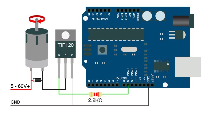
An Arduino digital I/O pin can output a maximum of 40mA. The total amount of current across all pins should not exceed 500mA. It is good practice not to power DC motors directly from a digital I/O pin.
The easiest way to power a DC motor is by using an external power supply combined with a transistor used as a switch to switch the motor on/off. A transistor uses a small current flowing from the Base to the Emitter to create a conductive path between the Collector and Emitter. It is a bit like how the first small patch of loose snow moving down a mountain slope causes an avalanche. A TIP120 transistor (darlington pair) can handle 60V 5A across the Collector-Emitter junction and only needs 2mA applied to the Base-Emitter junction to create a short between Collector and Emitter, just like a switch. If you want to use Ohms law to calculate the current flowing through the resistor it helps to know that the Base-Emitter junction acts like a diode and has zero Ohm resistance as it is connected in forward bias (conducting) and has a 0.6Vdc voltage drop.
 Instead of a transistor a (solid state) relay can be used to switch more powerful DC motors.
Hardware Required
- Arduino Board
- 2.2k Ohm resistor
- TIP120 power transistor
- DC motor
- Diode
- DC power supply
Code
Example 1
int motorPin = 8;

void setup()
{
    pinMode(motorPin, OUTPUT);
}

void loop()
{
    digitalWrite(motorPin,HIGH);
    delay(3000);
    digitalWrite(motorPin,LOW);
    delay(1000);
}
Example 2
The following example uses an analog pin as output and asks the user to provide a number between 0 and 255 that is then translated to an output voltage of 0V…5Vdc on analog pin A0. This is a simple way of controlling the speed of the motor by varying the voltage.
int motorPin = A0;

void setup()
{
  pinMode(motorPin, OUTPUT);
  Serial.begin(9600);
  while (! Serial);
  Serial.println("Speed 0 to 255");
}


void loop()
{
  if (Serial.available())
  {
    int speed = Serial.parseInt();
    if (speed >= 0 && speed <= 255)
    {
      analogWrite(motorPin, speed);
    }
  }
}
ULN2003A
This integrated circuit (chip) consisting of an array of 7 transistors (darlington pair) can be used to switch on/off up to 7 DC motors. Freewheel diodes are included. Note that this chip uses inverted logic; a LOW on an input pin will make the corresponding output pin HIGH.
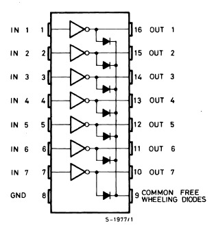
This chip is often used in combination with unipolar stepper motors.
Code
The same code as in the previous example can be used. Simply duplicate the code to include additional pins.
H-bridge using L298N or A3967 (EasyStepper)
H-bridge integrated circuits can not only switch on/off up to 2 DC motors, but can also change the polarity making the motor spin clockwise or anti-clockwise. This chip is often used in combination with bipolar stepper motors.
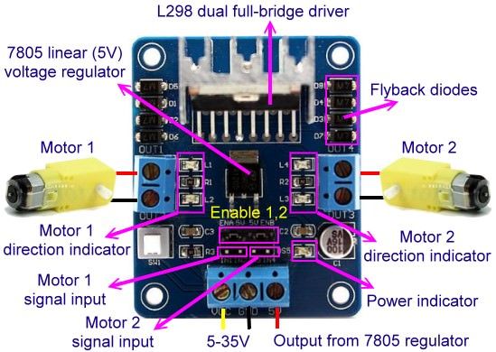
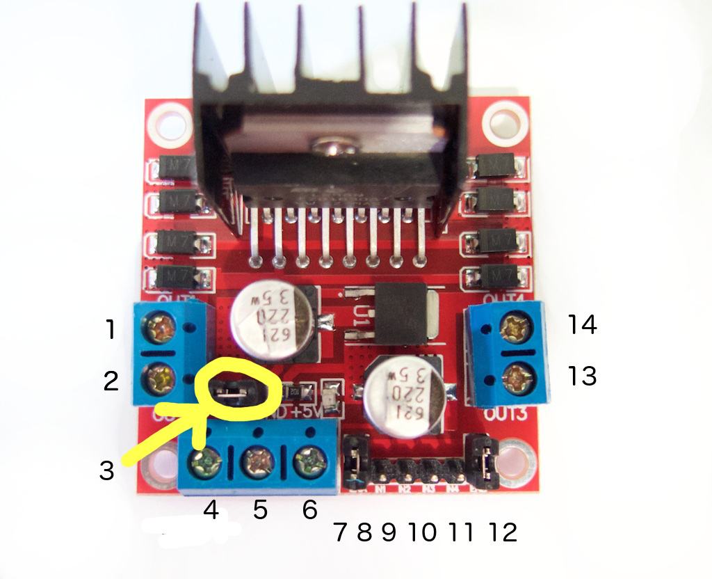
Pinout
- DC motor 1 “+” or stepper motor A+
- DC motor 1 “-” or stepper motor A-
- 12V jumper – remove this if using a supply voltage greater than 12V DC. When the jumper is in place, the onboard voltage regulator is active (12V max to 5V).
- Connect your motor supply voltage here, maximum of 35V DC. Remove 12V jumper if >12V DC
- GND
- 5V output if the 12V jumper at #3 is in place. This is ideal for powering your Arduino.
- DC motor 1 enable jumper. Leave this in place when using a stepper motor. Connect to PWM output for DC motor speed control.
- IN1
- IN2
- IN3
- IN4
- DC motor 2 enable jumper. Leave this in place when using a stepper motor. Connect to PWM output for DC motor speed control.
- DC motor 2 “+” or stepper motor B+
- DC motor 2 “-” or stepper motor B-
IN1 and IN2 control the direction of motor1 while IN3 and IN4 control the direction of motor2. EN1 drives motor1 and EN2 drives motor2. You can either use a fixed voltage (0..5Vdc)or use pulse width modulation (PWM).
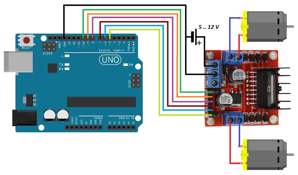
Circuit
Code
// connect motor controller pins to Arduino digital pins
// motor one
int enA = 10;
int in1 = 9;
int in2 = 8;
// motor two
int enB = 5;
int in3 = 7;
int in4 = 6;
void setup()
{
  // set all the motor control pins to outputs
  pinMode(enA, OUTPUT);
  pinMode(enB, OUTPUT);
  pinMode(in1, OUTPUT);
  pinMode(in2, OUTPUT);
  pinMode(in3, OUTPUT);
  pinMode(in4, OUTPUT);
}
void demoOne()
{
  // this function will run the motors in both directions at a fixed speed
  // turn on motor A
  digitalWrite(in1, HIGH);
  digitalWrite(in2, LOW);
  // set speed to 200 out of possible range 0~255
  analogWrite(enA, 200);
  // turn on motor B
  digitalWrite(in3, HIGH);
  digitalWrite(in4, LOW);
  // set speed to 200 out of possible range 0~255
  analogWrite(enB, 200);
  delay(2000);
  // now change motor directions
  digitalWrite(in1, LOW);
  digitalWrite(in2, HIGH);
  digitalWrite(in3, LOW);
  digitalWrite(in4, HIGH);
  delay(2000);
  // now turn off motors
  digitalWrite(in1, LOW);
  digitalWrite(in2, LOW);
  digitalWrite(in3, LOW);
  digitalWrite(in4, LOW);
}
void demoTwo()
{
  // this function will run the motors across the range of possible speeds
  // note that maximum speed is determined by the motor itself and the operating voltage
  // the PWM values sent by analogWrite() are fractions of the maximum speed possible
  // by your hardware
  // turn on motors
  digitalWrite(in1, LOW);
  digitalWrite(in2, HIGH);
  digitalWrite(in3, LOW);
  digitalWrite(in4, HIGH);
  // accelerate from zero to maximum speed
  for (int i = 0; i < 256; i++)
  {
    analogWrite(enA, i);
    analogWrite(enB, i);
    delay(20);
  }
  // decelerate from maximum speed to zero
  for (int i = 255; i >= 0; --i)
  {
    analogWrite(enA, i);
    analogWrite(enB, i);
    delay(20);
  }
  // now turn off motors
  digitalWrite(in1, LOW);
  digitalWrite(in2, LOW);
  digitalWrite(in3, LOW);
  digitalWrite(in4, LOW);
}
void loop()
{
  demoOne();
  delay(1000);
  demoTwo();
  delay(1000);
}
The procedure demoTwo() in the above code uses the analogWrite function to control the speed of a DC motor using Pulse Width Modulation (PWM) by varying the duty cycle of a signal.
Pulse width modulation (variable duty cycle)
Close your eyes. It is dark. Count to 10 repeatedly. At the count of 10, briefly open your eyes and immediately close them again. You will experience mostly darkness with an occasional flash of light.
Now open your eyes. It is light. Count to 10 repeatedly. At the count of 10, briefly close your eyes and immediately open them again. You will experience mostly light with an occasional flash of darkness. And possibly a slight headache.
Now imagine doing this really fast. Too fast for your eyes to register. Just like the 24 frames per second of a television screen or the 50Hz flicker of a fluorescent light bulb we see a smooth animation. Your eyes will simply average out the frames and you will experience either see dim light or bright light.
We can use this to dim a LED or change the speed of a DC motor. We can send a LED or a DC motor pulses of a fixed duration (T), for example 0.1 milliseconds – which translates to 10.000 pulses per second,or 10kilohertz. For one pulse, we can then make it mostly LOW (narrow pulse) or mostly HIGH (wide pulse). As the frequency of the pulses is very high, the DC motor will simply see the average voltage.
This is an excellent way to control LED brightness or DC motor speeds and eliminates the problem of having to provide a higher start-up current to make the motor spin from standstill.
The duty cycle indicates the ratio between a signal being HIGH versus LOW:
One of the benefits of DC motors is that the voltage is directly proportional with rotation speed. If the voltage drops below a certain point you will have difficulties making the motor spin from standstill. Pulse width modulation is a an effective way of controlling DC motor speed and eliminates the need for a higher start-up current to make the motor spin from standstill.
Code
Example of a 30% duty cycle:
void loop() {
  digitalWrite (pin,HIGH);
  delay (10);
  digitalWrite (pin,HIGH);
  delay (10);
  digitalWrite (pin,HIGH);
  delay (10);
  digitalWrite (pin,LOW);
  delay (10);
  digitalWrite (pin,LOW);
  delay (10);
  digitalWrite (pin,LOW);
  delay (10);
  digitalWrite (pin,LOW);
  delay (10);
  digitalWrite (pin,LOW);
  delay (10);
  digitalWrite (pin,LOW);
  delay (10);
  digitalWrite (pin,LOW);
  delay (10);
}
There is however an easier way to do this:
/*
  Fade

  This example shows how to fade a LED on pin 9
  using the analogWrite() function.

  The analogWrite() function uses PWM, so if
  you want to change the pin you're using, be
  sure to use another PWM capable pin. On most
  Arduino, the PWM pins are identified with
  a "~" sign, like ~3, ~5, ~6, ~9, ~10 and ~11.

  This example code is in the public domain.
  */

 int led = 9;           // the PWM pin the LED is attached to
 int brightness = 0;    // how bright the LED is
 int fadeAmount = 5;    // how many points to fade the LED by

 // the setup routine runs once when you press reset:
 void setup() {
   // declare pin 9 to be an output:
   pinMode(led, OUTPUT);
 }

 // the loop routine runs over and over again forever:
 void loop() {
   // set the brightness of pin 9:
   analogWrite(led, brightness);

   // change the brightness for next time through the loop:
   brightness = brightness + fadeAmount;

   // reverse the direction of the fading at the ends of the fade:
   if (brightness <= 0 || brightness >= 255) {
     fadeAmount = -fadeAmount;
   }
   // wait for 30 milliseconds to see the dimming effect
   delay(30);
 }