Arduino + LCD(16×2)
Description
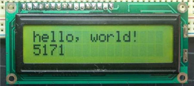
The LiquidCrystal library allows you to control LCD displays that are compatible with the Hitachi HD44780 driver. There are many of them out there, and you can usually tell them by the 16-pin interface. This example sketch prints “Hello World!” to the LCD and shows the time in seconds since the Arduino was reset.
Pinout
The LCDs have a parallel interface, meaning that the microcontroller has to manipulate several interface pins at once to control the display. The interface consists of the following pins:
- A register select (RS) pin that controls where in the LCD’s memory you’re writing data to. You can select either the data register, which holds what goes on the screen, or an instruction register, which is where the LCD’s controller looks for instructions on what to do next.
- A Read/Write (R/W) pin that selects reading mode or writing mode.
- An Enable pin that enables writing to the registers.
- 8 data pins (D0 -D7). The states of these pins (high or low) are the bits that you’re writing to a register when you write, or the values you’re reading when you read.
- There’s also a display constrast pin (Vo), power supply pins (+5V and Gnd) and LED Backlight (Bklt+ and
BKlt-) pins that you can use to power the LCD, control the display contrast, and turn on and off the LED backlight, respectively.
The process of controlling the display involves putting the data that form the image of what you want to display into the data registers, then putting instructions in the instruction register. The LiquidCrystal Library simplifies this for you so you don’t need to know the low-level instructions.
The Hitachi-compatible LCDs can be controlled in two modes: 4-bit or 8-bit. The 4-bit mode requires seven I/O pins from the Arduino, while the 8-bit mode requires 11 pins. For displaying text on the screen, you can do most everything in 4-bit mode, so example shows how to control a 2×16 LCD in 4-bit mode.
Hardware Required
- Arduino Board
- LCD Screen (compatible with Hitachi HD44780 driver)
- 10k Potentiometer
- breadboard
- hook-up wire
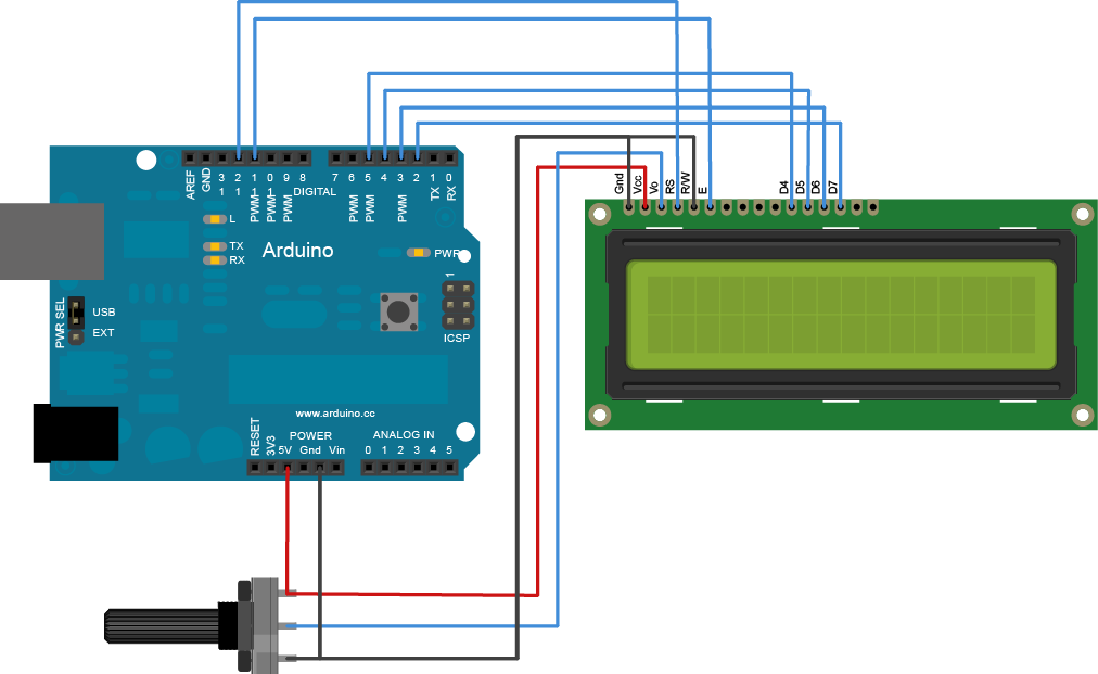
Circuit
To wire your LCD screen to your Arduino, connect the following pins:
- LCD RS pin to digital pin 12
- LCD Enable pin to digital pin 11
- LCD D4 pin to digital pin 5
- LCD D5 pin to digital pin 4
- LCD D6 pin to digital pin 3
- LCD D7 pin to digital pin 2
- Additionally, wire a 10K pot to +5V and GND, with it’s wiper (output) to LCD screens VO pin (pin3).
Code
// include the library code:
#include <LiquidCrystal.h>

// initialize the library with the numbers of the interface pins
LiquidCrystal lcd(12, 11, 5, 4, 3, 2);

void setup() {
    // set up the LCD's number of columns and rows:
    lcd.begin(16, 2);

    // Print a message to the LCD.
    lcd.print("hello, world!");
 }

void loop() {
    // set the cursor to column 0, line 1
    // (note: line 1 is the second row, since counting begins with 0):
    lcd.setCursor(0, 1);

    // print the number of seconds since reset:
    lcd.print(millis()/1000);
 }
Description
You can purchase “LCD Keypad shield” boards that include a 2×16 LCD display and 6 momentary push buttons. The board uses a Hitachi HD44780 character LCD driver chip and as such is compatible with the LiquidCrystal library.
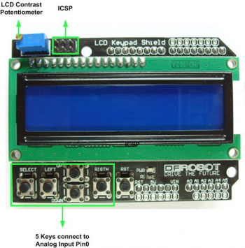
This shield has 5 pushbuttons — select, up, right, down and left which allow you move through menus and make selections. Most of these boards use a resistor ladder circuit connected to analog pin A0. This allows all 5 pushbuttons to be controlled by a single pin on the Arduino board.
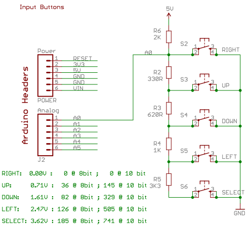
If no button is being pressed the voltage on A0 will be pulled all the way up to 5V by the 2K resistor called R6. In that situation none of the other resistors have any effect at all, and the analog reading on A0 will be close to 1023. If you perform an analogRead() call on A0 and it returns 1023 (or any value above about 1000) you know that no buttons are being pressed.
Now consider what happens if the “DOWN” button is pressed. Now A0 is being presented with a voltage that is divided between the 2K Ohm resistor that is trying to pull it up to 5V, and the 330 Ohm (R2) and 620 Ohm (R3) resistors in series (totaling 950 Ohm) that are trying to pull it down to 0V. The voltage presented to A0 in that case is about 1.61V (representing a value of 329). If you perform an analogRead() on pin A0 and it returns a value of about 329 you know the “DOWN” button is being pressed.
The same principle applies for the other buttons, with the voltages and equivalent analogRead() values shown in the schematic.
Hardware Required
- Arduino Board
- LCD Keypad shield
Pinout
- D4-D7 – LCD Data pins
- D8 – Register Select (RS) pin
- D9 – Enable (E) pin
- D10 – Backlight pin (PWM)
Circuit
Simply carefully press the LCD Keypad shield on top of the Arduino board ensuring correct pin alignment.
Important
The LCD Keypad shield often ships using a “blue backlight with white characters” character LCD display. However, the LCD panel’s contrast control (a current limiting multi-turn trim pot) often needs to be twisted many turns clockwise (10-20 turns or so) before you can properly see any text.
Code
Example 1
// include the library code:
#include <LiquidCrystal.h>

// initialize the library with the numbers of the interface pins
LiquidCrystal lcd(8, 9, 4, 5, 6, 7);

void setup() {
  // set up the LCD's number of columns and rows:
  lcd.begin(16, 2);
  // Print a message to the LCD.
  lcd.setCursor(0,0);
  lcd.print("LCD Key Shield");
  lcd.setCursor(0,1);
  lcd.print("Press Key:");
}

void loop() {
  int x;
  x = analogRead (0);
  lcd.setCursor(10,1);
  if (x < 60) {
    lcd.print ("Right ");
  }
  else if (x < 200) {
    lcd.print ("Up    ");
  }
  else if (x < 400){
    lcd.print ("Down  ");
  }
  else if (x < 600){
    lcd.print ("Left  ");
  }
  else if (x < 800){
    lcd.print ("Select");
  }
}
Example 2
/*************************************************************************************

  This program will test the LCD panel and pushbuttons.
  When you push the pushbutton on the shield the display will show what button was pressed.

**************************************************************************************/

#include <LiquidCrystal.h>

LiquidCrystal lcd(8, 9, 4, 5, 6, 7);           // select the pins used on the LCD panel

// define some values used by the panel and buttons
int lcd_key     = 0;
int adc_key_in  = 0;

#define btnRIGHT  0
#define btnUP     1
#define btnDOWN   2
#define btnLEFT   3
#define btnSELECT 4
#define btnNONE   5

int read_LCD_buttons(){               // read the buttons; return a number representing the button pressed
    adc_key_in = analogRead(0);       // read the value from the sensor

    // my buttons when read are centered at these values: 0, 144, 329, 504, 741
    // we add approx 50 to those values and check to see if we are close

    if (adc_key_in > 1000) return btnNONE;

    // For V1.1 us this threshold
    if (adc_key_in < 50)   return btnRIGHT;
    if (adc_key_in < 250)  return btnUP;
    if (adc_key_in < 450)  return btnDOWN;
    if (adc_key_in < 650)  return btnLEFT;
    if (adc_key_in < 850)  return btnSELECT;

    return btnNONE;                // when all others fail, return this.
}

void setup(){
   lcd.begin(16, 2);               // start the library
   lcd.setCursor(0,0);             // set the LCD cursor   position
   lcd.print("Push the buttons");  // print a simple message on the LCD
}

void loop(){
   lcd.setCursor(9,1);             // move cursor to second line "1" and 9 spaces over
   lcd.print(millis()/1000);       // display seconds elapsed since power-up

   lcd.setCursor(0,1);             // move to the begining of the second line
   lcd_key = read_LCD_buttons();   // read the buttons

   switch (lcd_key){               // depending on which button was pushed, we perform an action

       case btnRIGHT:{             //  push button "RIGHT" and show the word on the screen
            lcd.print("RIGHT ");
            break;
       }
       case btnLEFT:{
             lcd.print("LEFT   "); //  push button "LEFT" and show the word on the screen
             break;
       }
       case btnUP:{
             lcd.print("UP    ");  //  push button "UP" and show the word on the screen
             break;
       }
       case btnDOWN:{
             lcd.print("DOWN  ");  //  push button "DOWN" and show the word on the screen
             break;
       }
       case btnSELECT:{
             lcd.print("SELECT");  //  push button "SELECT" and show the word on the screen
             break;
       }
       case btnNONE:{
             lcd.print("NONE  ");  //  No action  will show "None" on the screen
             break;
       }
   }
}
Example 3
In addition to the current limiting trim pot, you can also change the backlight brightness from inside your code as well. By using pulse width modulation (PWM) we vary the duty cycle of pin D10 resulting in an average voltage between 0V and 5V to change the brightness of the backlight.
I would recommend to first adjust the trim pot until you have a properly functioning LCD display and only then use the following example to experiment with varying the backlight brightness:
void setup()
{
}

void loop()
{
  int i;
  for (i = 0; i < 256; i++)
  {
    analogWrite(10, i); //pin D10
    delay(10);
  }
  for (i = 255; i > 0; i--)
  {
    analogWrite(10, i);  //pin D10
    delay(10);
  }
}