Arduino + Stepper (Theory)
Description
Stepper motors are DC motors that move in discrete steps. They have multiple coils that are organized in groups called “phases”. By energizing each phase in sequence, the motor will rotate, one step at a time.
A stepper motor has the following characteristics:
- rotation in both directions,
- precision angular incremental changes,
- repetition of accurate motion or velocity profiles,
- a holding torque at zero speed, and
- capability for digital control.
A stepper motor can move in accurate angular increments knows as steps in response to the application of digital pulses to an electric drive circuit from a digital controller. The number and rate of the pulses control the position and speed of the motor shaft. Generally, stepper motors are manufactured with steps per revolution of 12, 24, 72, 144, 180, and 200, resulting in shaft increments of 30, 15, 5, 2.5, 2, and 1.8 degrees per step.
Types of stepper motors
- Variable Reluctance
- Permanent Magnet
- Hybrid
Wiring of stepper motors
Stepper motors are either wired bipolar or unipolar.
Bipolar
- Always uses a 4 wire connection terminal.
- Coils consist of a single winding of relatively thick wire.
- Excellent holding force (torque)
- Requires reversing of the polarity; current needs to flow in both directions in order to create N-S pole and S-N pole electromagnet alternatively
- Needs H-bridge driver circuit to reverse polarity.
- Internal construction consists of 2 phases using 4 coils in series each.
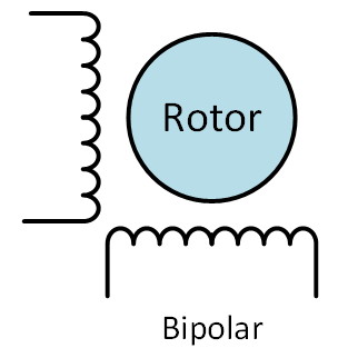
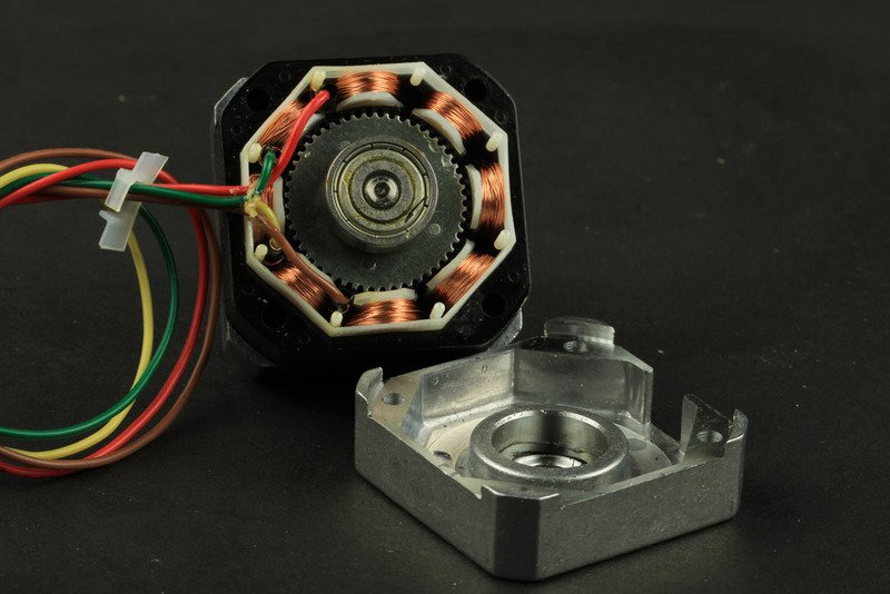 4 Wire (= Bipolar) 2 phase 4 coils (per phase) stepper motor
Unipolar
- Always uses either a 5,6 or 8 wire connection terminal.
- !! All unipolar stepper motors can be driven as bipolar for increased torque !!
- 2 phases consisting of 4 coils in series each.
- Each coil is wound using two windings (bifilar) instead of a single winding. Two opposite ends of each winding are connected together and act as center tap. This effectively results in a coil where one half acts as a N-S pole magnet and the other half as a S-N pole magnet.
- Reduced holding torque.
- Easy to drive.
- Internal construction consists of 2 phases using 4 coils in series each.
Unipolar 5 wire
This style is common in smaller unipolar motors. All of the common coil wires are tied together internally and brought out as a 5th wire.
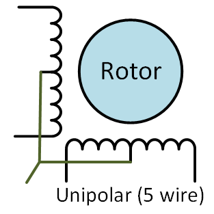
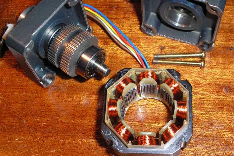 5 Wire (= Unipolar) 2 phase 4 coils (per phase) stepper motor
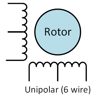
6 Wire (Unipolar)
- Same as 5 wire unipolar with the exception that the common leads are not joined.
- These two wires can be joined externally to create a 5-wire unipolar motor.
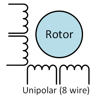
8 Wire (Unipolar)
The 8-wire unipolar is the most versatile motor of all. It can be driven in several ways:
- 4-phase unipolar – All the common wires are connected together – just like a 5-wire motor.
- 2-phase series bipolar – The phases are connected in series – just like a 6-wire motor.
- 2-phase parallel bipolar – The phases are connected in parallel. This results in half the resistance and inductance – but requires twice the current to drive. The advantage of this wiring is higher torque and top speed.
Let’s have a look at how to drive stepper motors, starting with the bipolar stepper motor.
Stepping – Bipolar
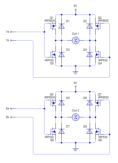
Driver Circuit (Bipolar) – dual H-Bridge
We can use a single H bridge circuit to drive a simple DC motor. By reversing the polarity (= reversing the direction of current flowing through the coil) we can make a motor spin both clockwise or counterclockwise.
We need to use two H-bridge circuits (dual H-bridge) to drive both coils of a bipolar stepper motor.
How does a H-bridge circuit work?
The field effect transistors (FET) Q1 to Q4 act like switches. The diodes D1 to D4 act like freewheeling diodes to channel back-electromagnetic force (back-EMF) of the motor coils. When the ‘switches’ Q1 and Q4 are closed (and Q2 and Q3 are open) a conducting path is created and current will flow from +9Vdc to Q1 to the coil to Q4 to GND. By opening Q1 and Q4 switches and closing Q2 and Q3 switches, a different conducting path is generated from +9Vdc to Q2 to the coil to Q3 to GND. If you pay close attention you will notice the current flowing through the coil in the opposite direction, allowing reverse operation of the motor.
Note however the switches Q1 and Q2 should never be closed at the same time, as this would cause a short circuit. The same applies to the switches Q3 and Q4. This is why we cannot simply use Arduino HIGH and LOW outputs to reverse the polarity; a H-bridge circuit is essential.
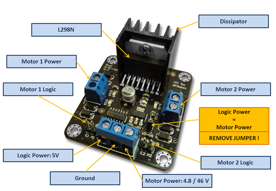
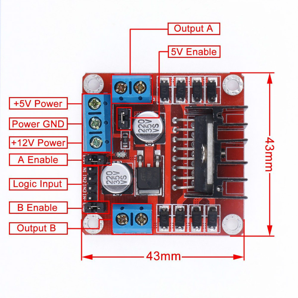
A popular driver board is the L298N dual H-bridge board:
- Dual H-bridge.
- Can be used to control bipolar stepper motor.
- Can be used to control 2 DC motors and revere polarity for change in direction.
- Staggered-lead, through-hole package that can be used with breadboards.
- Operation to 46 V
- Up to 2 A per channel.
- Outputs can be paralleled to drive up to 3 A
- Independent ground connections for each channel allow independent current sensing.
- Does not have built-in flywheel diodes.
Another popular bipolar (+unipolar) driver board is the EasyDriver board based on an Allegro A3967 dual H bridge chip.
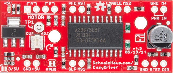
http://www.schmalzhaus.com/EasyDriver
- Maximum current of 750mA per phase of a bi-polar stepper motor.
- Maximum stepper motor voltage of around 30V.
- On-board 5V regulation.
- Defaults to 8 step microstepping mode – so if your stepper motor is 200 full steps per revolution, you would get 1600 steps/rev using EasyDriver.) This setting can be easily overridden by tying the MS1 and/or MS2 pin to ground to set the driver to use 1/8, 1/4 or 1/2 microstep mode
- Chopper microstepping driver based on the Allegro A3967 driver chip.
- Cheap.
Let’s have a look at unipolar stepper motors next. Remember, unipolar stepper motors have bifilar wound coils that make these motors simple to drive (no reverse polarity required) at a cost of reduced torque.
Stepping – Unipolar
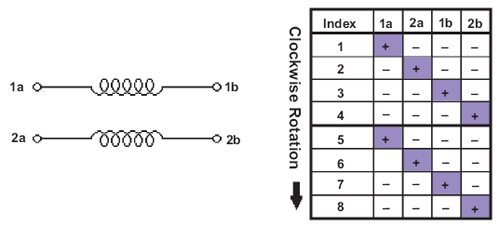
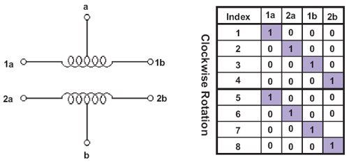
Unipolar Full Step
Note: The “common” leads (a,b) will always have the same voltage (i.e. GND). The other leads (1a, 1b, 2a 2b) are then switched on and off in a logical sequence.
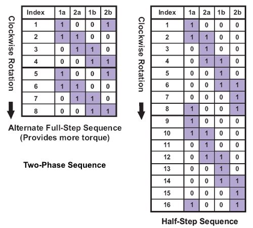
Unipolar Step Variations
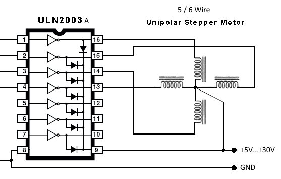
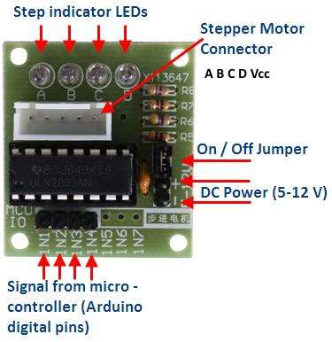
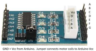
Driver Circuit (Unipolar)
Note that the ULN2003A inverts the logical inputs. By connecting the common lead to +5V…+30V instead of GND we can counteract this logic inversion.