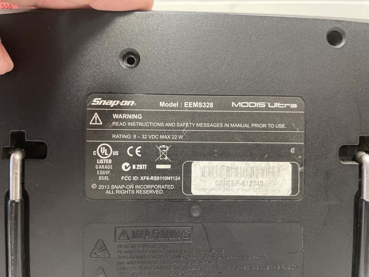
Snapon Modis Ultra – Real time clock (RTC) – set the date
(Click on pictures to enlarge).
Credits to EEVblog and forum members for doing most of the hard work. Thank you for sharing information and photos:
https://www.eevblog.com/forum/beginners/snap-on-automotive-scan-tool-system-date-not-set-in-flash-memory/25/
[!] Before making any changes, remove the microSD card from the slot and insert into a card reader on a computer. The microSD card is formatted as FAT32 and contains a number of hidden files and folders. Enable show hidden files/folders and copy & paste contents to your computer as a backup.
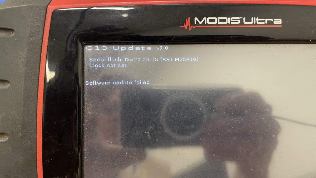
Do not connect to Snap-on Shop Stream Connect as this may put the device in update mode. If the device date is not set i.e. real time clock chip ‘seconds’ counter value equals zero corresponding with a date of 1 Jan 1970, the update will fail, reporting ‘Clock not set’. This will effectively brick the device with no option to return to the normal boot sequence. Users can only set the time, but not the date. Snap-on will not reprogram the date into the device as device is considered outdated. At this point your only option is to program the date into the onboard real time clock chip.
During normal use, if the real time clock chip date is not set, or the chip loses power and the date is reset, the device will present a message when connecting to a vehicle over the OBD connector with a countdown timer before allowing the user to continue.
Disassembly
Remove microSD card to prevent it catching on the plastic case.
Remove large flathead screws to access battery pack. Remove small screw holding battery pack in place. Slide battery pack up to unlatch and remove.
Remove Philips head screws from back to disassemble the case. There is 1 screw located underneath the stand bracket.
Remove the oscilloscope circuit board.
Remove the oscilloscope base plate held in place with a single screw.
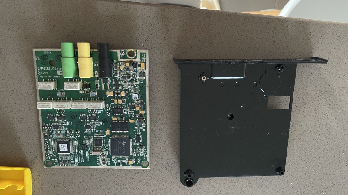
Note the 3 metal prongs on the right hand side in below image where the rechargeable battery pack is located. This battery is what allows portable use of the device. There is also a DC power connector that accepts 8-32Vdc from a mains powered AC/DC adapter. Snap-on AC/DC Adapter – Part# 2-60666A 19Vdc/3A.
You can power up the device using the AC/DC adapter even with battery pack, microSD card, and oscilloscope board removed.
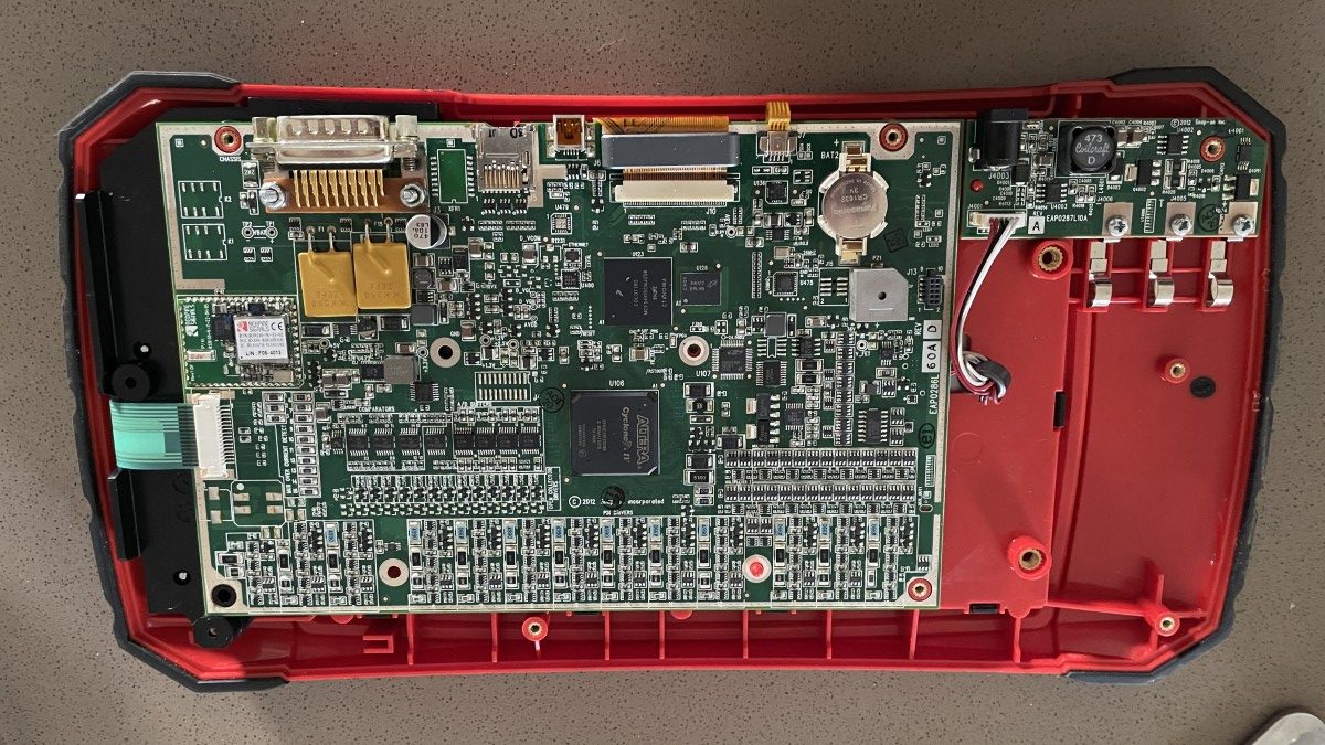
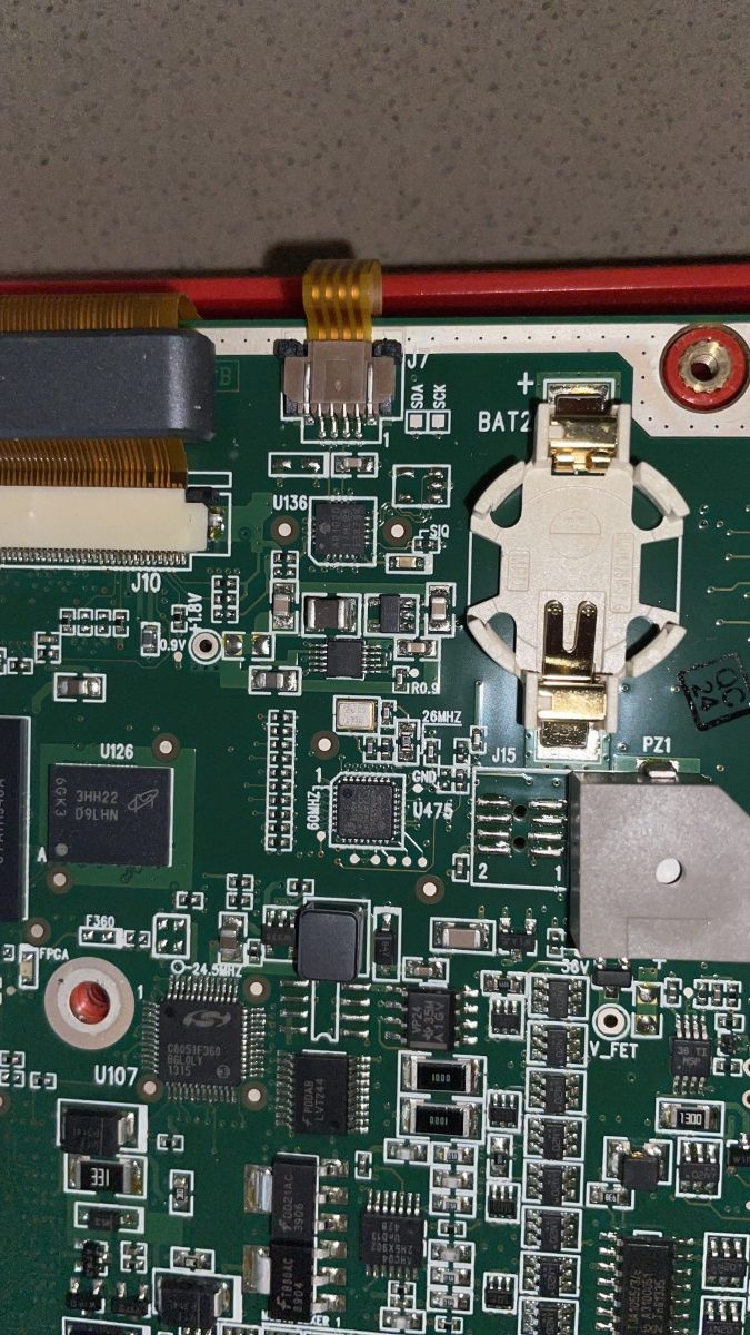
To prevent the real time clock chip from losing power, there is a 3V button battery present:
Panasonic CR1632 3V. You can simply pry it out of the battery holder as it is held in place with spring clips. You can measure the battery voltage using the spring clips in-circuit, or remove and measure top/bottom of button battery. Battery voltage should be 3V at all times.
If this button battery no longer holds charge, and power is removed from the device, the device will lose the set date value with no option for the end user to set the date.

Service menu
Press and hold both the Cancel/No button (‘X’) as well as the Confirm/Yes button (‘Y’).
Press and hold the Power On/Off button.
Wait for the device to boot and only then release all three buttons.
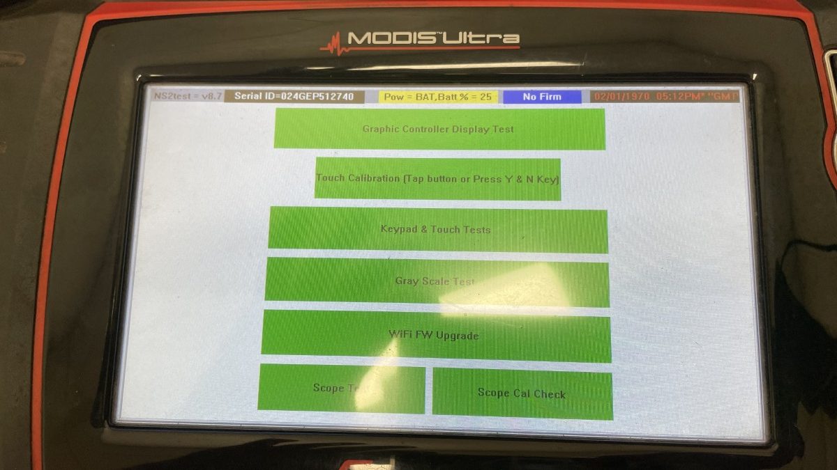
You will be presented with a Service menu showing a Utilities option (Connect to PC) as well as an NS2TEST boot option.
The NS2TEST boot option will allow basic hardware diagnostics of the device.
Note that time is displayed in GMT and the NS2TEST boot option does not do time zones, so the time may be displayed offset from local time even if the date/time was set correctly. Image shows real time clock chip date is not set. You cannot set/program the date here.
Connect to PC
[!] This is not required to set the date on the device. Do not use.
This will not synchronize the date between computer and device. This is only useful to update the device. There are no more updates for this device available. Subscription service may show as ‘Expired’. There is no subscription service required for low level firmware upgrades. The latest software version you can transfer to the device (firmware upgrade) is supposedly v25.2. Make sure to have a copy of your microSD card as it contains information unique to your device. Copying a microSD card from another device will likely not work.
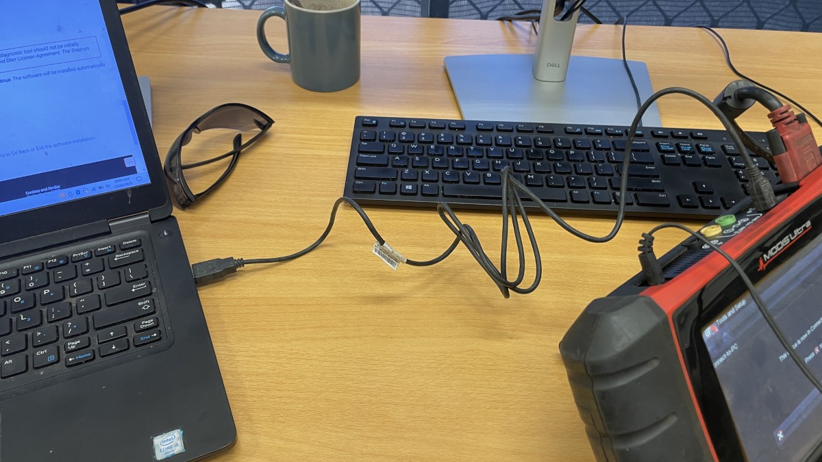
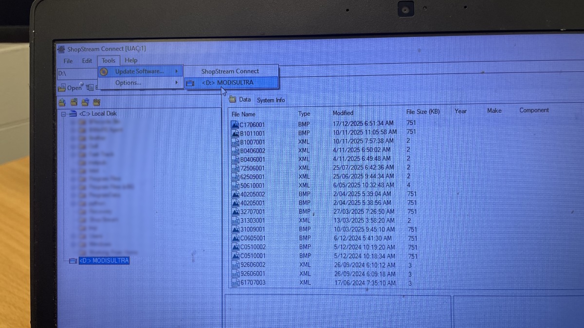
Download and install Snap-on ShopStream Connect application.
Select the option to Connect to PC.
The software will show a list of files on the device’s micoSD card.
Note that it only shows files from the USERDATA folder on the microSD card.
At this point you can use Windows file explorer with hidden files visible to copy and paste the entire contents of the memory stick to create a backup if need be. It is easier and faster to use a microSD card reader as the USB connection is slow. Total size of all files and folders on the SD Card is 1GB+.
You can check for updates. Note this will likely put the device in firmware update boot mode with no option to cancel that I know of.
In my case I ended up with ‘Clock not set’ and ‘Software update failed’ with no option to return to normal boot sequence.
Programming the onboard real time clock chip
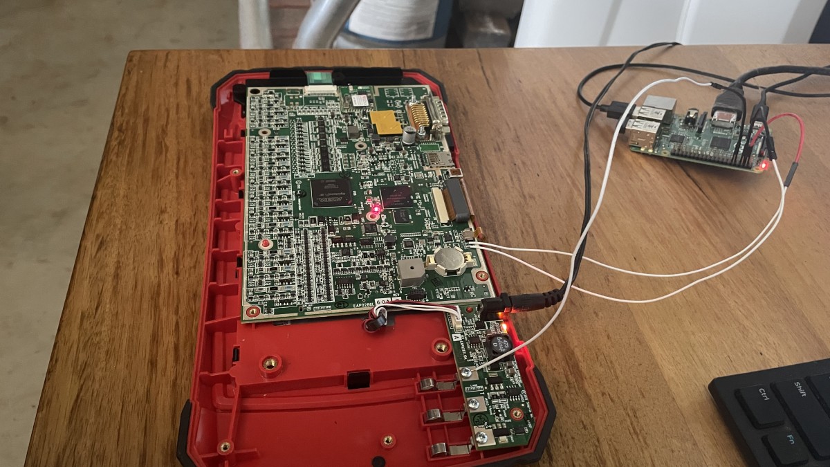
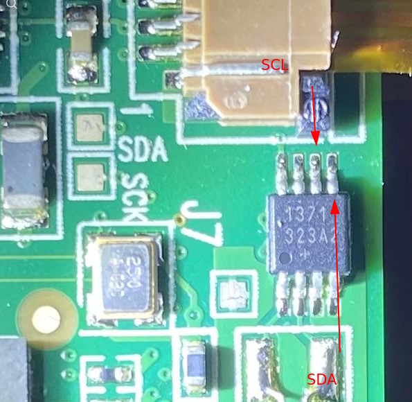
Note the I2C communication bus solder pads on the circuit board labelled SDA and SCK. SDA is used to transfer ones and zeros (‘DATA’), and SCK is used as clock pulse (‘CLOCK’). You can use a Raspberry Pi or Arduino to talk over the I2C bus. I2C data and clock on the Pi are named SDA and SCL. The only requirement to use this interface is to have both your Raspberry Pi (or Arduino) and the Snap-on Modis Ultra device connected to the same ground, so all voltage levels are respective to common ground.
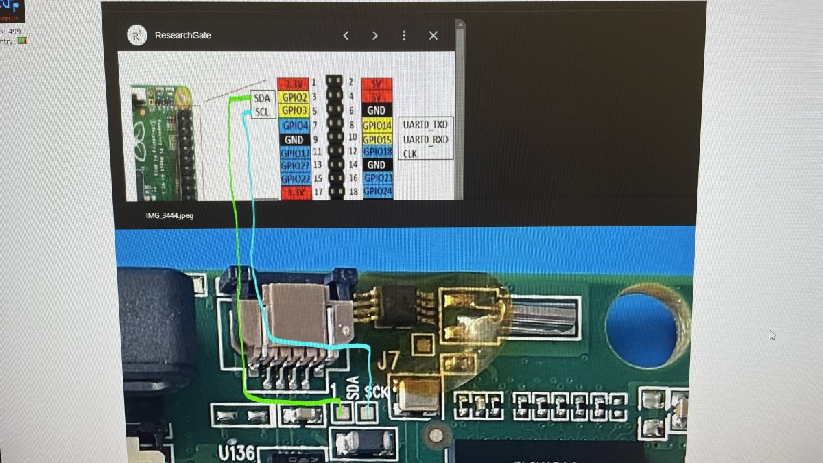
Here you see a Raspberry Pi connected to SDA, SCK/SCL and GND. The battery pack screw terminal is on the same ground voltage level as the button battery ‘-‘ terminal and easy to use with a new and tested 3V button battery present.
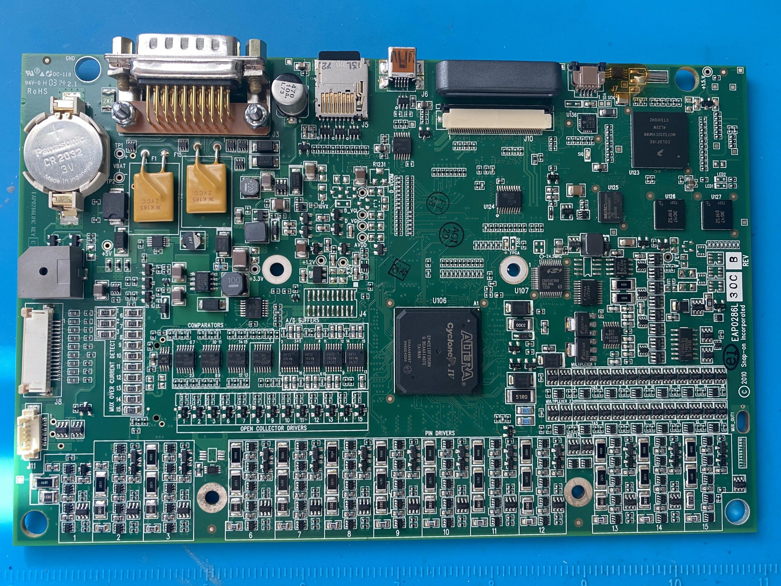
The Snap-On Modis Ultra EEMS328 uses a DS1371 real time clock chip, same as similar Snap-on vehicle diagnostics tools (Zeus, Solus Ultra) . You may be able to spot this chip on the circuit board. The required oscillator crystal, 3V Vcc, and GND are already present – no other parts are needed.
For example – images from EEVblog internet post – click to enlarge.
https://www.eevblog.com/forum/beginners/snap-on-automotive-scan-tool-system-date-not-set-in-flash-memory/25/
DS1371 RTC chip located under yellow Kapton tape:
Setup your Raspberry Pi
Download and run Raspberry Pi Imager for Windows.
Run and complete the quick configuration steps to optionally configure a WiFi connection.
Transfer Raspberry Pi OS Lite to a blank microSD card or USB memory stick (only newer Raspberry Pi v4 / v5 boards can boot directly from USB memory stick) to boot your Raspberry Pi.
I connected to my Raspberry Pi using USB keyboard and HDMI monitor using command line interface.
No full desktop required. No SSH required.
An internet connection is needed (wired or wireless).
sudo apt update
sudo apt upgrade
sudo apt install i2c-tools util-linux-extra
sudo raspi-config
Use the arrow keys, tab key, enter key, escape key to navigate to ‘Interface options’ and ‘Enable I2C’.
Do not edit “/boot/firmware/config.txt” and do not add “dtoverlay=i2c-rtc,ds1307″ or similar as this is not needed and may complicate things (‘device is busy’ when manually entering commands).
This instruction is only required if you want to use a Real Time Clock chip every time the Raspberry Pi boots.
Instead, we will probe manually and on-the-fly.
sudo reboot
sudo dmesg | grep -i rtc
There is likely no message in the Rapberry Pi system/boot log relating to an Real Time Clock chip (‘rtc’) at this time.
We can use i2cdetect to scan for I2C devices:
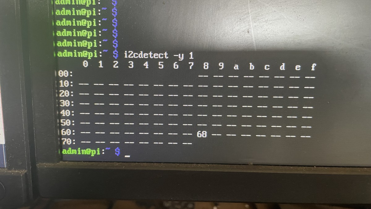
There is a chip responding on I2C address 0x68 showing a value of ’68’.
’68’ = Device or resource busy.
‘UU’ = This address is currently in use by a driver.
Internet forum posts suggest the following:
DS1371 is different from the more common / basic DS1307 and cannot be programmed the same way.
DS1371 is very similar to DS1374 and can be programmed the same way.
DS1374 drivers are present in Rapberry Pi OS and do not require downloading.
To enable DS1374 driver (which will autodetect hardware):
sudo modprobe rtc-ds1374
echo ds1374 0x68 | sudo tee /sys/class/i2c-adapter/i2c-?/new_device
This no longer works on Debian Trixie 13 as ‘/sys/class/i2c-adapter/…’ is now ‘/sys/class/i2c-dev/devices/…’
Note: ‘/sys/class/i2c-dev/devices/’ and ‘sys/bus/i2c/devices/’ appear to be symbolic links to the same location and can be used interchangeably.
How is this supposed to work?
sudo modprobe rtc-ds1374
This will enable DS1374 driver and detect any DS1374 (or compatible e.g. DS1371) real time clock chip over I2C.
sudo dmesg | grep -i rtc
This should report a new device ‘/dev/rtc0’ being detected.
sudo i2cdetect -y 1
This should detect a real time clock chip on I2C address 0x68.
As we know, this device communicates on address 0x68. We will need to tell the driver.
On Raspberry Pi OS Debian Trixie 13 or newer:
echo ds1374 0x68 | sudo tee /sys/class/i2c-dev/devices/i2c-?/new-device
which is basically the same as:
echo ds1374 0x68 | sudo tee /sys/class/i2c-dev/devices/i2c-1/new-device
echo ds1374 0x68 | sudo tee /sys/class/i2c-dev/devices/i2c-2/new-device
…
or we can use:
sudo bash
This will give us a root user shell (similar to sudo).
echo ds1374 0x68 > /sys/class/i2c-dev/devices/i2c-1/new-device
This will allow us to write directly to the driver class file.
As there is only a single I2C chip detected, we can be relatively certain /dev/rtc0 corresponds with /i2c-1/
If in doubt, do the same for /i2c-2/
Now, to write the system date/time to the real time clock chip:
date
Shows current system date/time.
hwclock -r
hwclock -r -v
Reads date/time value rom DS1371 real time clock chip (using DS1374 driver).
hwclock -w
hwclock -w -v
Writes current system date/time to DS1371 real time clock chip (using DS1374 driver).
If we repeat hwclock -r (-v) we should see the date/time was successfully updated.
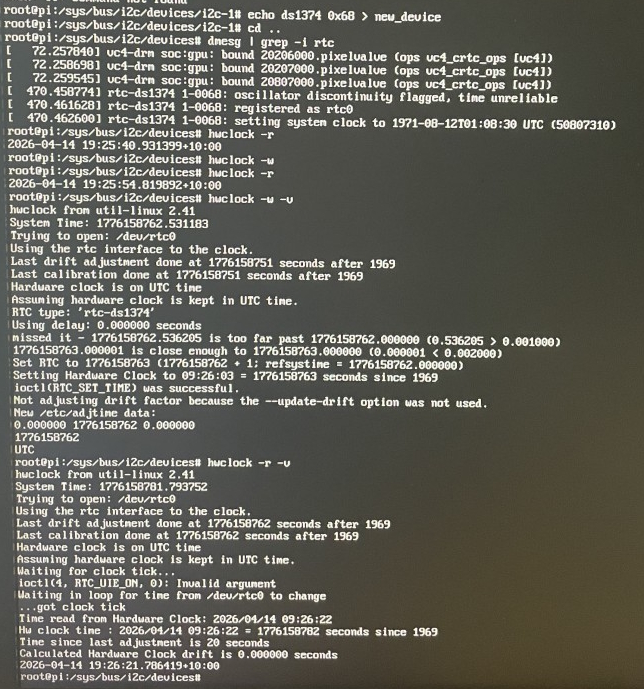
In above image the current date had already been programmed into the real time clock chip prior to taking a screenshot.
If the date/time does not ‘stick’ when you power cycle your Modis Ultra device:
It may be that the real time clock chip is ‘device is busy’ as the Modis Ultra may talk over I2C and keep it busy. Try booting the Snap-On device into Service mode, or remove the microSD card temporarily. Then, repeat the previous instructions to see of the real time clock chip is not ‘busy’.
It is important that hwclock in verbose mode (-v) shows RTC type: ‘rtc-ds1374’ to indicate the correct driver is being used.
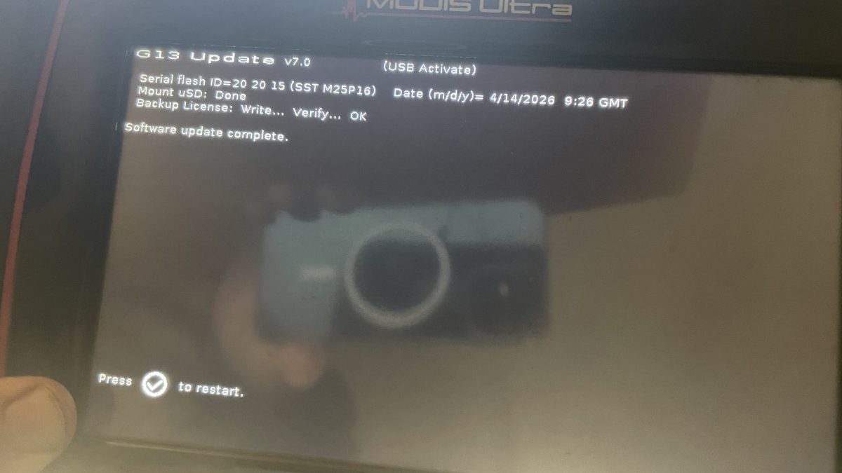
After all this, software update was complete, without making any noticeable changes. Software revision remained identical, with date/time set correctly. Time zone was configured in system settings. Device appears to be functioning properly without alerts or warnings.
Disclaimer
This article explains how to set the date on an outdated device when the internal button battery has failed. It does not circumvent nor tamper with any copy protection, nor violate intellectual property rights.