MPCNC part 7
When cutting 6mm HDPE in a single pass, I experienced lost steps and a glitching sound when steppers were kept enabled after the job had completed:
- GRBL is arguably better suited to CNC milling operations than Marlin (position updates during arcs, better compatibility with CNC.js).
- Geeetech GTK2560 v3.0 board uses an Arduino Mega. I learned the Protoneer CNC Shield uses an Arduino Uno which is more than fast enough. Arduino Mega offers no benefits over Arduino Uno when it comes to sending step/dir signals to stepper motor drivers (stepsticks).
- Geeetech GTK2560 v3.0 board was setup for 1/32 micro-stepping. 1/16 micro-stepping might improve torque at cost of accuracy. Accuracy is still tens of mm, so should be fine.
- I like a shield that can be removed / replaced easily.
- I like standard Dupont 2.54mm pitch header pins for everything.
- I like that there is no micro-fuse like on the Geeetech board, not that this is used in this application (bed heater). SKR Pro board uses readily available automotive mini fuses.
- I like that you can update grbl through Arduino IDE onto Arduino Uno.
- I like that grbl allows you to set step/mm, max speed, acceleration from console and save into EEPROM. No need to edit config file and recompile / upload Marlin.
- I like that grbl is not as feature-rich as Marlin and supports fewer gcode instructions. Less to go wrong.
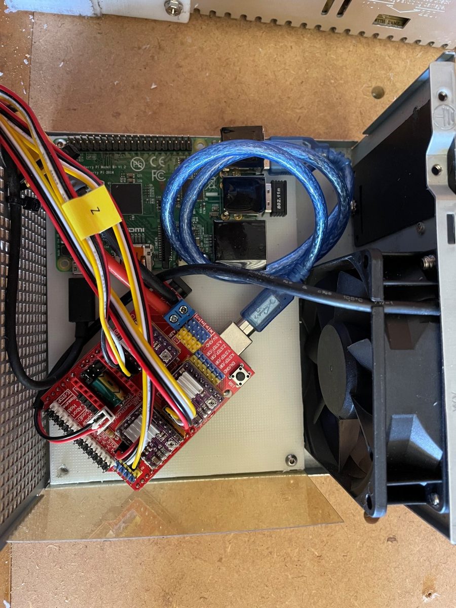
New hardware setup
Raspberry Pi CNC.js Wi-Fi accessible web interface to load Gcode with Arduino Uno + CNC Shield v3.0 + 3x DRV8825 stepsticks + series Y harness for X1/X2 + series Y harness for Y1/Y2 + 1/16 micro-stepping + 24Vdc fan.
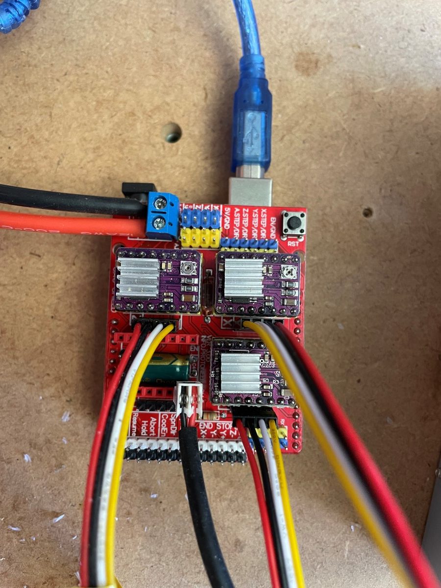
Protoneer CNC Shield v3.10 is latest. I got a CNC Shield v3.00 from fleabay. Compatible with grbl v0.8 / 0.9 protoneer website says. I am just going with latest grbl 1.1h as I don’t use variable speed spindle or endstops. Be warned there are also some weird ‘unofficial’ versions like v4.00 on offer that have room for an Arduino Nano (not a shield) at a cost of only 3 instead of 4 stepstick ports.
Download latest Arduino IDE.
Download GRBL as ZIP: https://github.com/gnea/grbl
Extract and put the grbl folder inside grbl-Latest in its own ZIP fle.
ArduinoIDE -> Sketch -> Include Library -> Add .ZIP Library…
ArduinoIDE -> File > Examples > grbl > grblUpload
Upload
Serial monitor 115200 should give grbl prompt.
ALWAYS connect a stepper motor to the CNC Shield when testing. Stepper drivers are designed to ramp up the current until it reaches the current needed to run. Without a stepper motor connected there will be nothing to consume the current and you can end up damaging the stepper driver if it over-heats in the process.
AVOID moving the gantry by hand as this induces a current in the stepper motor that can damage the stepsticks. I just switch off the stepper motor 24V power supply and move the gantry gently.
1/16 microstepping is suggested.
For DRV8825 this means:
MS1 = Low
MS2 = Low
MS3 = High
For the CNC shield:
High = jumper
Low = no jumper
Pins are labelled left to right M0 M1 M2
So 1x jumper on M2
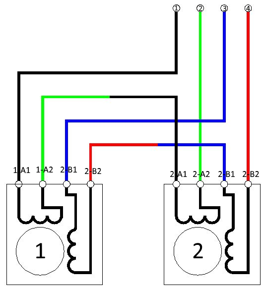
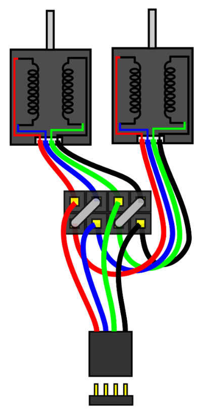
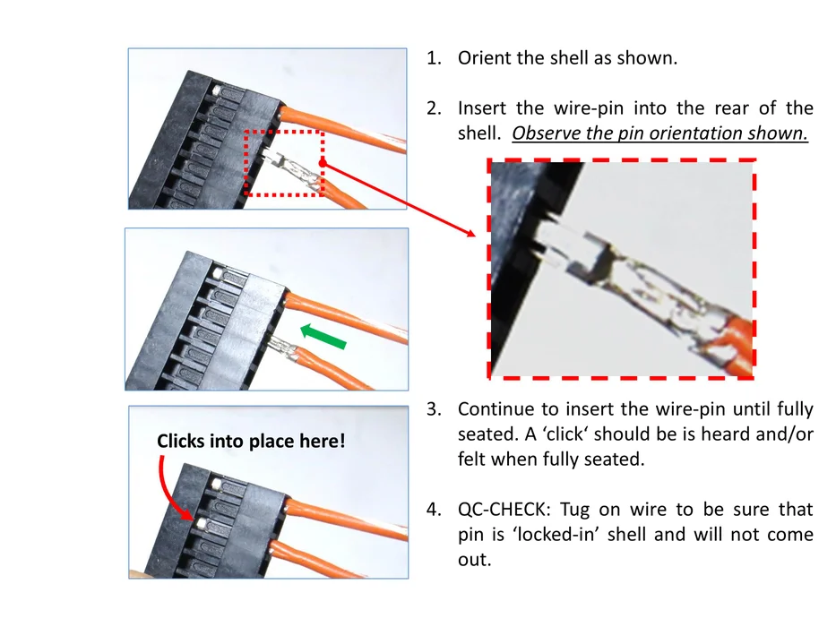
Stepper motor series Y harness
What is confusing most people is things like
“what if the wiring colors on my steppers are swapped / different”, or
“what if the direction the motor spins is not correct”, or
“the way the steppers are mounted, one of the steppers needs to spin in the opposite direction”.
As long as the pin-out of the stepper motor is such that the coil terminals are side-by-side, which they typically are, this schematic will work for you.
Note the steppers will indeed need to spin in opposite directions on an MPCNC machine.
– If one stepper is reversed, just flip the connector of that one stepper.
– If both steppers are reversed, just flip the Y harness connector where it plugs into the CNC shield affecting both stepper motors.
I first tried this approach:
https://www.instructables.com/Wiring-Your-Z-Stepper-Motors-in-Series/
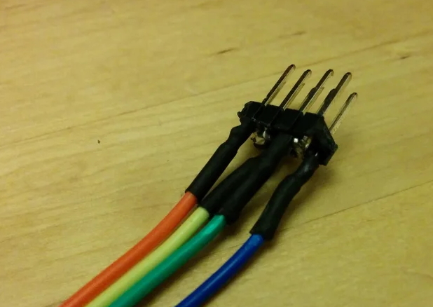
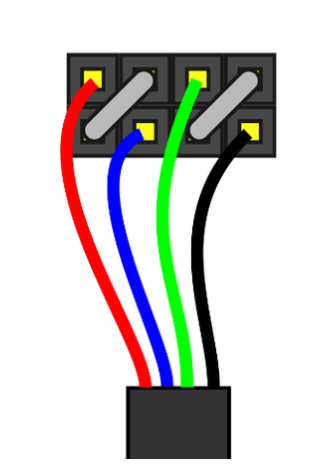
2×4 pin header as seen from the back:
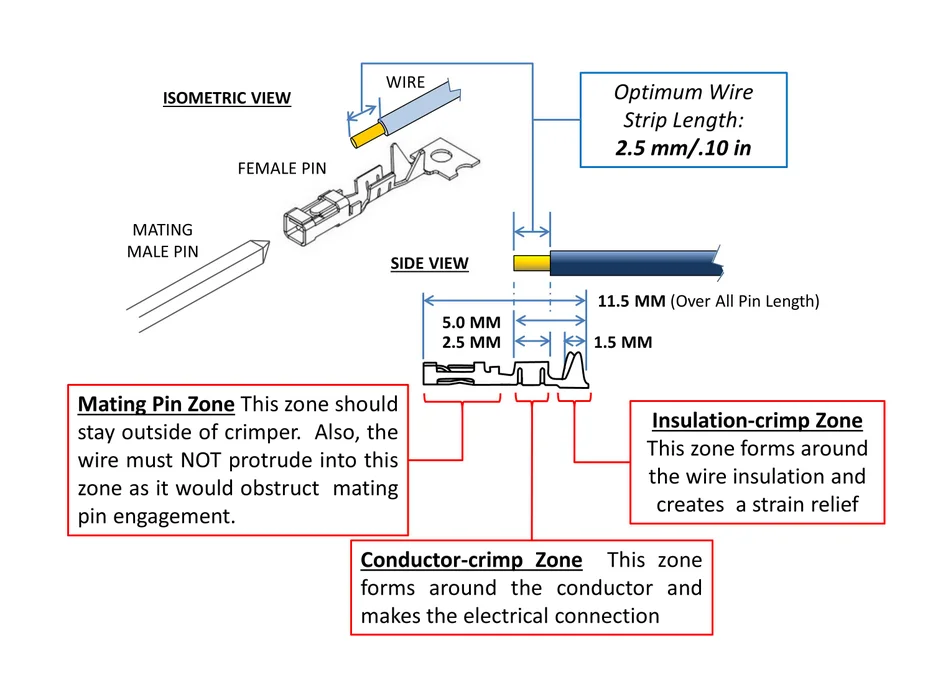
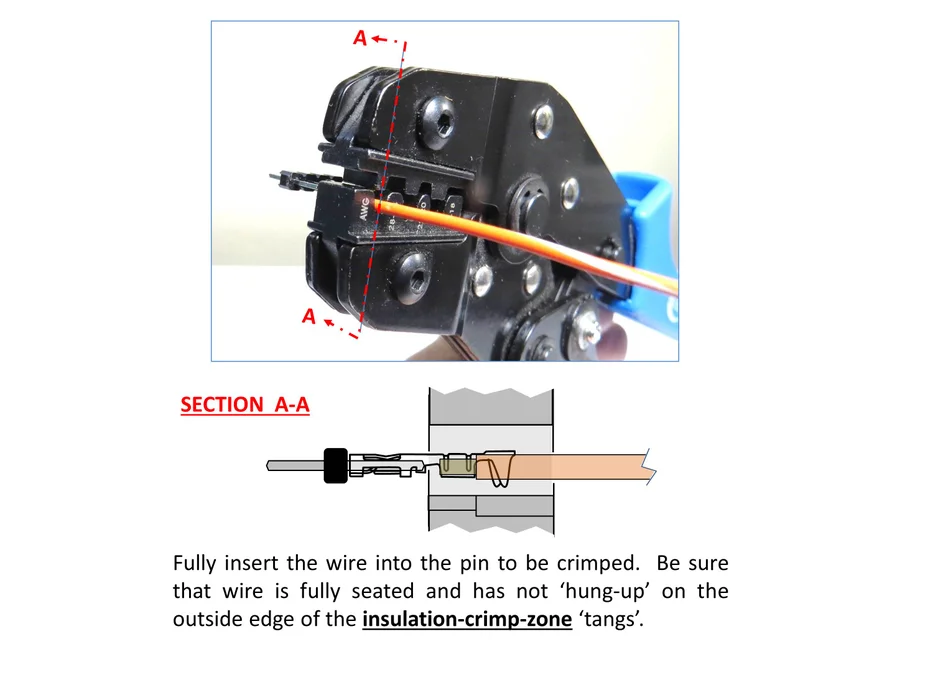
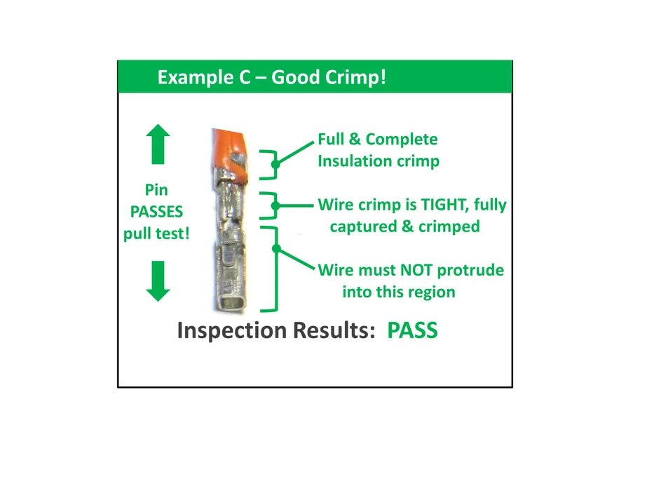
Instead, I used a crimping tool and made this cable:
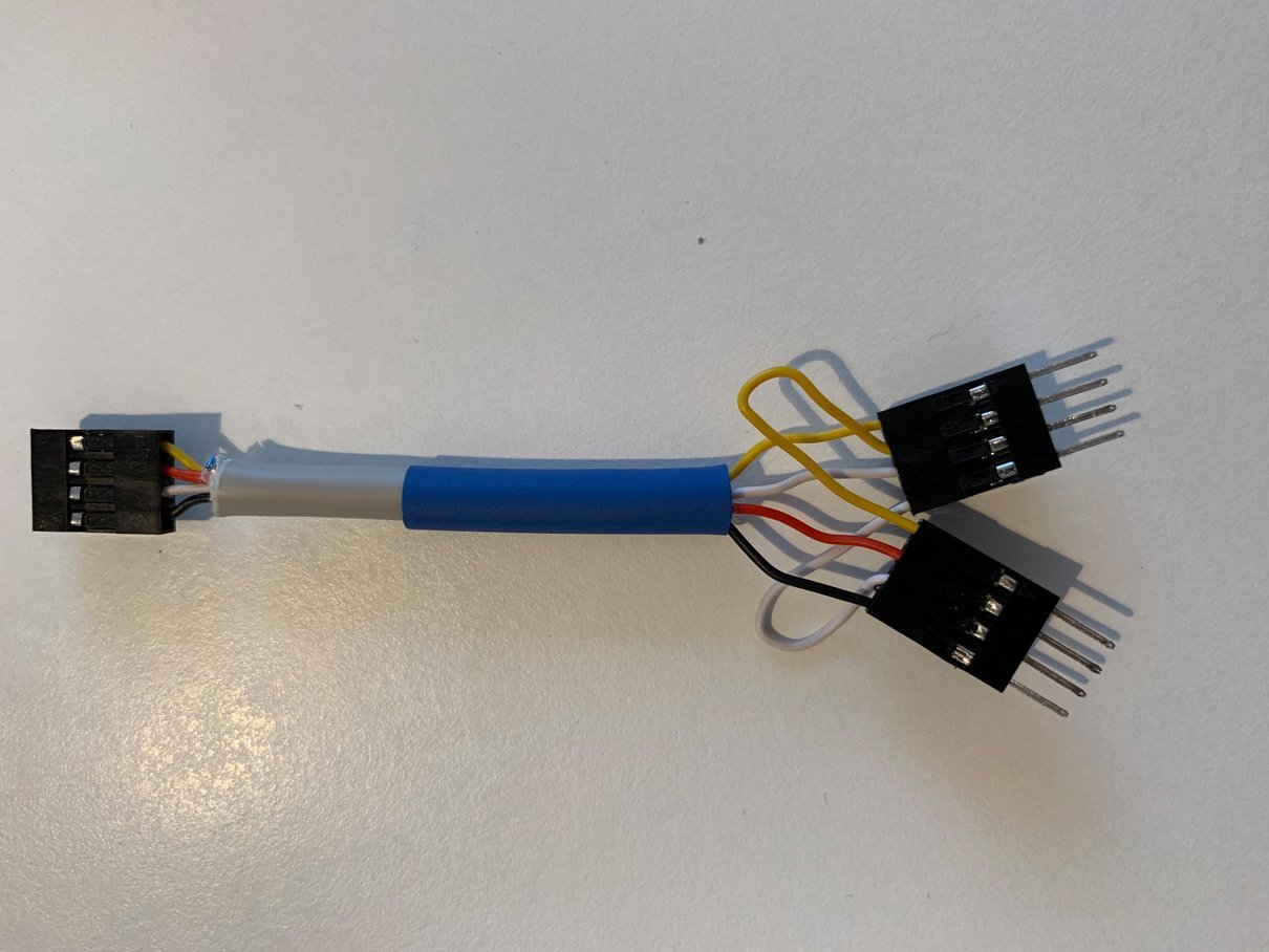
I used heat shrink to ensure the connections could not vibrate loose.
https://www.instructables.com/Make-a-Good-Dupont-Pin-Crimp-EVERY-TIME/
Calibrating steps/mm
Out of the box without any changes:
CNCjs 1.9.20 [Grbl]
Connected to /dev/ttyUSB0 with a baud rate of 115200
Grbl 1.1h ['$' for help]
client> $$
$0=10 (Step pulse time, microseconds)
$1=25 (Step idle delay, milliseconds)
$2=0 (Step pulse invert, mask)
$3=0 (Step direction invert, mask)
$4=0 (Invert step enable pin, boolean)
$5=0 (Invert limit pins, boolean)
$6=0 (Invert probe pin, boolean)
$10=1 (Status report options, mask)
$11=0.010 (Junction deviation, millimeters)
$12=0.002 (Arc tolerance, millimeters)
$13=0 (Report in inches, boolean)
$20=0 (Soft limits enable, boolean)
$21=0 (Hard limits enable, boolean)
$22=0 (Homing cycle enable, boolean)
$23=0 (Homing direction invert, mask)
$24=25.000 (Homing locate feed rate, mm/min)
$25=500.000 (Homing search seek rate, mm/min)
$26=250 (Homing switch debounce delay, milliseconds)
$27=1.000 (Homing switch pull-off distance, millimeters)
$30=1000 (Maximum spindle speed, RPM)
$31=0 (Minimum spindle speed, RPM)
$32=0 (Laser-mode enable, boolean)
$100=250.000 (X-axis travel resolution, step/mm)
$101=250.000 (Y-axis travel resolution, step/mm)
$102=250.000 (Z-axis travel resolution, step/mm)
$110=500.000 (X-axis maximum rate, mm/min)
$111=500.000 (Y-axis maximum rate, mm/min)
$112=500.000 (Z-axis maximum rate, mm/min)
$120=10.000 (X-axis acceleration, mm/sec^2)
$121=10.000 (Y-axis acceleration, mm/sec^2)
$122=10.000 (Z-axis acceleration, mm/sec^2)
$130=200.000 (X-axis maximum travel, millimeters)
$131=200.000 (Y-axis maximum travel, millimeters)
$132=200.000 (Z-axis maximum travel, millimeters)
ok
Online calculator
https://swarfer.co.za/cnc/grblcalc.html
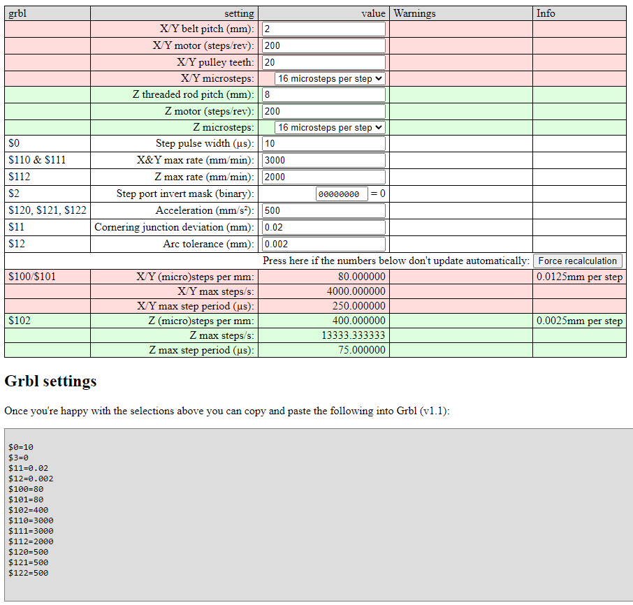
GT2 Belt 6mm –> 10mm Wide, Neoprene Rubber With Fiberglass Core (not steel), 2mm pitch.
X/Y belt pitch (mm): 2
X/Y motor (steps/rev): 200 (= 1.8 deg /step)
X/Y pulley teeth: 20
X/Y microsteps: 16
T8*2 (200mm) Lead Screw and Nut T8 4 start threads, 2mm pitch, 8mm/rev
Z threaded rod pitch (mm): 8
Z motor (steps/rev): 200 (= 1.8 deg /step)
Z microsteps: 16
Copy the following into GRBL console to save new defaults to EEPROM:
$0=10
$3=0
$11=0.02
$12=0.002
$100=80
$101=80
$102=400
$110=3000
$111=3000
$112=2000
$120=500
$121=500
$122=500
Verify by measuring actual distance travelled. Check gantry clearance(!)
G0 X500
G0 Y500
G0 Z50
G0 X0 Y0 Z0
I noticed very smooth acceleration and deceleration. Crown test completed successfully. grbl does not keep stepper motors energized after job finishes to allow drivers to cool down.
Fusion360 GRBL post processor
The following Marlin commands are not supported by grbl:
- Using semi-colon for comments. Uses () instead.
- M84 (disable steppers)
- M400 (finish moves, wait until buffer is empty)
- M117 (set LCD message)
Just grab a Fusion360 post processor from the Autodesk library:
https://www.autodesk.com/products/fusion-360/blog/fusion-360-grbl-post/
Waiting for Z wire extension
check gantry level with new spoilboard
Z height drop:
– calibrate vref voltage on drv8825
– swap out drv8825
– swap out stepper
The V1 specified 4-start lead screw moves at 8mm per turn. A 2-start lead screw moves at 4mm per turn, so it doubles the torque. A 1-start lead screw moves at 2 mm a turn, so it quadruples the torque. Going to an alternate lead screw will reduce your max feedrate and requires you to adjust steps/mm
Suggestions for improvement:
Upgrade 6mm GT2 belt to 10mm GT2 belt (fiberglass core)
Upgrade totem belt adjusters
https://www.thingiverse.com/thing:1125216
Totem_GT2_belt_clip_adjuster__1125216.zip
no. cable ties are low-tech but kiss and easier to service.