ESP8266 ESP-12E big digits NTP clock with date, time, temperature, humidity, pressure (barometer)
ESP32 vs ESP12 boards
ESP32 boards are more powerful and come with interesting onboard features. ESP32 boards are slightly more expensive and may differ between the different flavours:
- ESP32 boards (Wemos D1 mini, AiThinker)
- ESP32 TTGO LoRa32 SX1276 OLED
- ESP32 TTGO T-Camera with PIR sensor and OLED display (and microphone).
https://en.wikipedia.org/wiki/ESP32
For our needs the ESP8266 ESP-12E boards suffice.
Components
The following components were used:
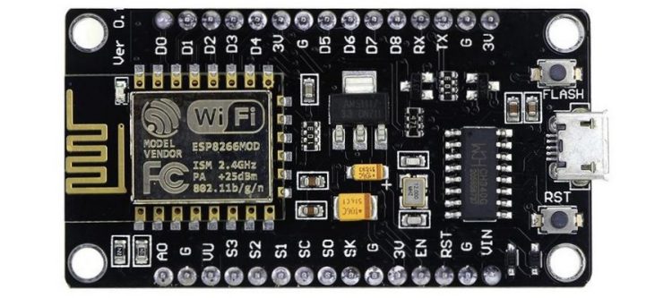
- NodeMCU ESP8266 ESP-12E V3 with CH340 USB-to-serial chip (or Silabs CP2102).
- 16×2 or 20×4 LCD (blue)
- I2C LCD backpack for 1602 and 2004
- Bosch I2C BME280 sensor.
https://en.wikipedia.org/wiki/ESP8266
The ESP8266 chip offers WLAN capabilities that Arduino boards do not offer. ESP-12E is the “12E” generation chip that is most common. “12F” has improved WLAN antenna design.
Datasheet ESP8266 ESP-12E
Pinout ESP8266 ESP-12E
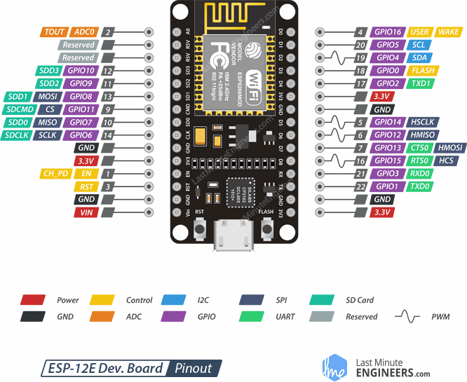
Pins
In code you typically use logical pin names like “5” for “GPIO5”. You can also use aliases (if defined in the board description file) like “D1” in this case. “SCL” is most likely not defined as an alias so you can’t use that. Physical pin numbers refer to the physical pins of the ESP8266 chip soldered on the breakout circuit board and are not used in code.
Vin
The Vin pin can be used to power a microcontroller from an external power source. If powered via USB, the Vin pin often connects directly to the USB +5V rail. Sometimes there is a diode in between as protection (resulting in a 0.5V voltage drop on the Vin pin) .
To power peripheral boards (Vcc and Gnd are often needed), you often borrow +5Vdc 500mA max from the Vin pin of a microcontroller when powered via USB.
NodeMCU ESP8266 ESP-12E ‘Lolin V3’ boards only offer +1.5Vdc on the Vin pin when powered via USB. Use the pin labelled ‘VV’ in white silkscreen text on the circuit board for +5Vdc instead.
I2C communication
Two-wire one-way communication bus using CL (= clock) and DA (= data) lines. Needs Vcc and GND to power slave boards.
SCL GPIO5
SDA GPIO4
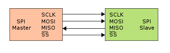
SPI communication
Four-wire two-way communication bus using:
CLK = clock
MOSI = master out slave in = master send
MISO = master in slave out = master receive
CS = chip select
Needs Vcc and GND to power slave boards.
ESP8266 boards have two SPI buses. Most code examples use the GPIO12-15 bus.
HSCLK GPIO14
HMISO GPIO12
HMOSI GPIO13
HCS GPIO15
SCLK GPIO6
MISO GPIO7
MOSI GPIO8
CS GPIO11
Getting started
A direct internet connection is required.
ArduinoIDE > Files > Preferences
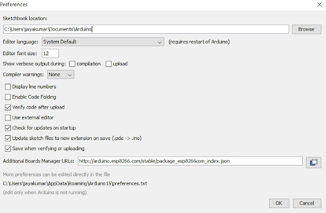
Enter the following ‘Additional Boards Manager URL’:
http://arduino.esp8266.com/stable/package_esp8266com_index.json
After completing the above steps , go to Tools > Board > Board Manager…
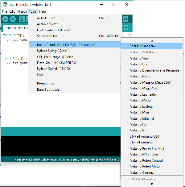
Navigate to esp8266 and install the software for Arduino.
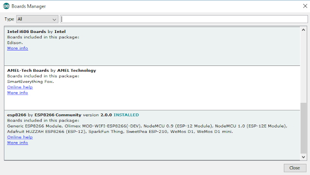
You can now upload code examples to NodeMCU ESP-12 boards.
Note: rename code example files to *.INO
Example – Blink
Blinks the built-in LED.
Most Arduino boards have a built-in onboard LED and a matching pin alias “LED_BUILTIN” you can use in code. NodeMCU ESP12 boards use GPIO2 / D4 or GPIO16 / D0.
You can change the port assignment for the “LED_BUILTIN” alias in the Arduino IDE on the fly. This needs to be set before (compiling and) uploading code to the board:
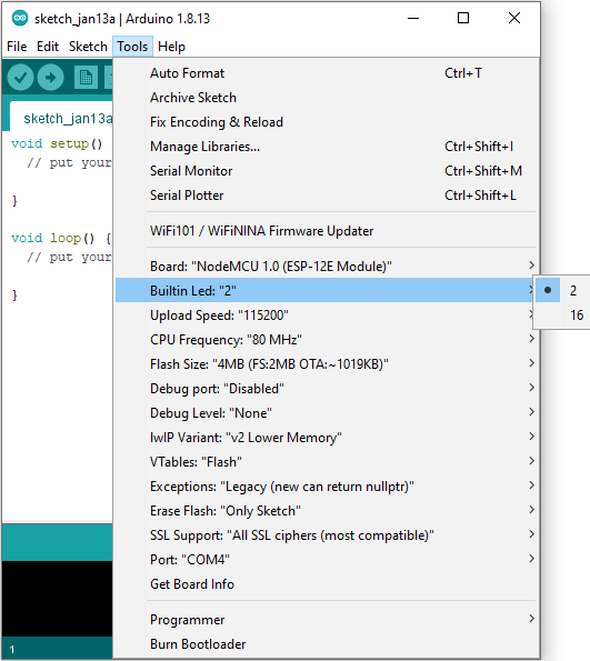
Remember NodeMCU ESP8266 boards use active low port logic as ports can only source 12mA of current but can sink much higher currents. Single color LEDs typically draw 1.2Vdc and 20mA of current. So when you send “HIGH” or “1” the pin will be internally pulled down to ground voltage level and current will start to flow into the pin.
Example – Web Blink
Same as before, but now we connect to the WLAN and run a web server. Check for the IP address of the ESP8266 board on your internet router and connect to the web page running on that IP address to toggle to LED status.
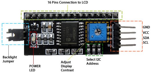
Example – I2C / SPI character LCD
We use a 16×2 character display connected to an LCD I2C backpack module. This module provides I2C / SPI two wire communication for 1602 to 2004 character LCD displays. This is used to save on the number of pins required to drive a typical Hitachi HD44780 character LCD display.
Most 16×2 LCD displays operate on 5Vdc, some may operate on 3Vdc.
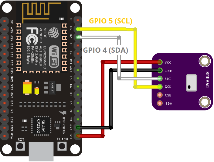
GND connects to ESP8266 pin GND
VCC connects to ESP8266 pin Vin for 5V or 3V3 for 3V
SDA connects to ESP8266 pin GPIO4
SCL connects to ESP8266 pin GPIO5
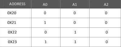
The default address for I2C / SPI communication is 0x27. You can change the address using A01 A1 A2 solder pads:
Important: The library LiquidCrystal_I2C suitable for ESP8266 boards can be found here:
https://github.com/fdebrabander/Arduino-LiquidCrystal-I2C-library
Download as ZIP and exrtact to folder “C:\Users\\<username>\My Documents\Arduino\libraries\LiquidCrystal_I2C\”
I2C scanner
This utility discovers I2C addresses on the I2C bus and reports them in plain text over the serial port.
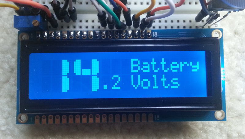
Example – I2C / SPI character LCD BigNums
LCD Custom Character Generator:
http://maxpromer.github.io/LCD-Character-Creator/
You can use this to generate a custom character:
You can use custom characters to build big numbers that cover two rows of a LCD character display:
A slightly different font:
1 | <a href="https://coeleveld.com/wp-content/uploads/2021/01/esp_i2c_lcd_bignums_002.txt">esp_i2c_lcd_bignums_002.txt</a> |
Big Font libraries
Example Big Font #1 – BigNumbers
https://github.com/seanauff/BigNumbers
Numbers only. Relatively simple to use. Feel free to replace library references to LiquidCrystal.h with LiquidCrystal_I2C.h
displayLargeNumber(number to display, column position first digit)

displayLargeInt(integer to display, column position first digit, number of digits to display for fixed length, display leading zeros true/false)

clearLargeNumber(column position topleft corner)
Example Big Font #2 – Custom Large Font
https://www.instructables.com/Custom-Large-Font-For-16×2-LCDs/
16x2_BigFont.txt
16x2_BigFont_table-lookup.txt
Complete font. First attempt at storing in a very efficient lookup table. Special case for wider-than-usual characters e.g. M,N,Q,V,W. Plain code; not an Arduino library on Github.
Example Big Font #3 – BigFont
Here someone created a 2×3, 3×3 and 4×4 font set for 20×4 character LCD displays. Contains preview images of what the fonts look like on an LCD screen, which is essential.
https://github.com/gcassarino/BigFont
20x4_BigFont.zip
Example Big Font #4 – Alpenglow Industries BigNums2x2
Contains 4 fonts with numbers only (Trek, Tron, Nasa, Serif). Code is easy to read. Library is available in Arduino Library Manager search. Does not contain wider-than-usual characters. Feel free to replace library references to LiquidCrystal.h with LiquidCrystal_I2C.h
https://www.alpenglowindustries.com/blog/the-big-numbers-go-marching-2×2
https://github.com/AlpenglowInd/BigNums2x2
Example – BME280 sensor
The Bosch BMW280 sensor measures temperature, humidity and barometric pressure (which can be used to calculate altitude based on a reference barometric pressure at sealevel value). Trends in barometric pressure are used to predict weather (rain/clouds versus sun/clear).
Note: most boards offer only I2C communication with SPI only available on slightly more expensive boards.
Sensors are quite accurate. Temperature is typically consistently 1.5 deg Celcius higher than actual due to internal heating of the integrated circuit. Simply compensate for this in code.
Using I2C communication:
Important: Adafruit_Sensor.h = Tools > Manage Libraries > Search > “adafruit” and select “Adafruit Unified Sensor by Adafruit”
To change the address, use the solder jumpers:
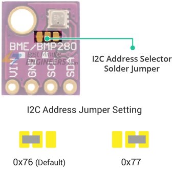
Note: Some boards do not have an I2C address selector solder jumper. For those boards a separate fifth pin labelled “SDO” needs to be connected to either GND or VDD. This pin should not be left floating. Connected to GND results in address (0x76); connecting to VDD results in address (0x77).
Example – NTP
This example fetches internet time and date using the time.h library at certain intervals:
Note: timezone value is the UTC offset e.g. Brisbane is UTC+10
WARNING: The BME280 board I used does not work with AdaFruit code. I had to use the “BME280 Library by Tyler Glenn” and the included example sketch from the Arduino library manager. This worked like a charm.
I then discovered boards sold on eBay as “BMP/BME280” are actually BMP280 boards. BMP280 boards lack a humidity sensor over BME280 boards.
Putting it all together
My own set of BigFont libraries:
https://coeleveld.com/bigfont/
Test using Arduino Uno 16×2 LCD keypad shield.
keypad_shield_bignums.txt
Test using ESP8266 16×2 LCD over I2C and NTP for date/time.
Using my own font libraries: BigFont01_I2C, BigFont02_I2C, etc.
esp_ntp_lcd.txt
BME280 and I2C 16×2 character display combined:
esp_i2c_bme280_i2c_lcd.txt
I have since abandoned this project as ordering parts from overseas has proven unreliable. I had purchased two white on black 16×2 LCDs (white on blue was too bright) but these took one month to arrive and due to a non-standard pinout I lost both LCDs and three I2C adapter boards. Combined with the BME280 sensor being only a BMP280 sensor I have lost enthusiasm for completing this project.