Arduino + Relay
Warning
Do NOT use this tutorial to connect a relay to 230Vac mains power. I have blown the cap of a LED by connecting it directly between +5Vdc and ground once. I have melted an electrolytic capacitor by connecting it to a voltage higher than it was rated for. There are not too many people with stories like these when it comes to 230Vac. 230Vac mains power poses a potentially lethal electrical shock hazard.
Description
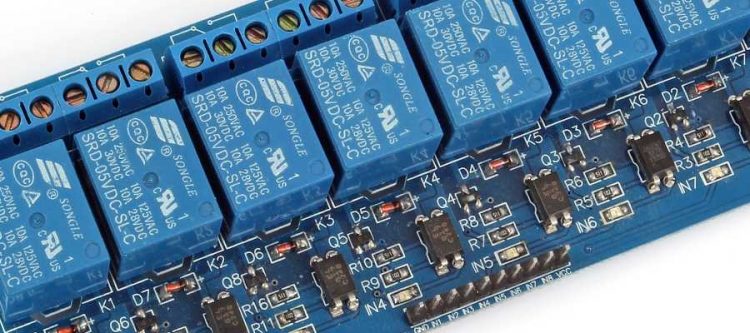
A relay is basically a mechanical switch operated by an electromagnet. The coil and coil terminals are completely isolated from the switch contacts (galvanic separation). This allows for switching of higher current / higher voltage electronic circuits.
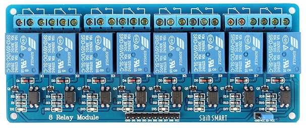
The SainSmart 8 Channel DC 5V Relay Module has the following features:
- 5Vdc 8-Channel Relay interface board
- Each relay coil requires 15-20mA driver current to toggle the switch.
- Equipped with high-current relay, AC250V 10A ; DC30V 10A
- Standard interface that can be controlled directly by microcontroller
- Indication LEDs for Relay output status
Hardware Required
- Arduino board
- SainSmart 8 Channel DC 5V Relay Module
- Hookup wire
Pinout
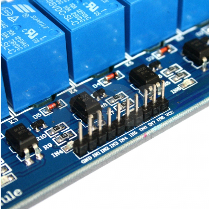
Logic terminal
- GND – Ground
- IN1 – Input1
- IN2 – Input2
- IN3 – Input3
- IN4 – Input4
- IN5 – Input5
- IN6 – Input6
- IN7 – Input7
- IN8 – Input8
- VCC – +5Vdc supply voltage (optocoupler LED only)
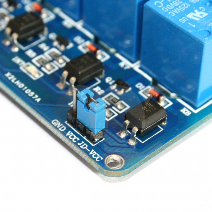 Power terminal
- GND – Ground
- Vcc – +5Vdc supply voltage (optocoupler LED only)
- JD-Vcc – +5Vdc >200mA external power supply (relay coils)
Vcc versus JD-Vcc
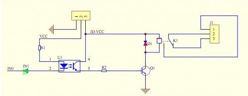
A relay coil requires 20mA to open. An Arduino digital I/O pin can drive 40mA max (and around 20mA nominal). The relay module allows you to use a separate power supply to drive the relay coils. Optocouplers are in use to isolate the Arduino output pins from the circuit driving the relay coils. An optocoupler consists of a LED that shines light on a light-sensitive transistor. The transistor will conduct if the LED is lit. The main purpose of an optocoupler is to isolate a circuit (galvanic separation). Can’t we just skip the relays then and just use beefed-up optocouplers you may ask? Optocouplers are only suited for low power applications. The transistor in an optocoupler can only handle small currents.
So how does it work?
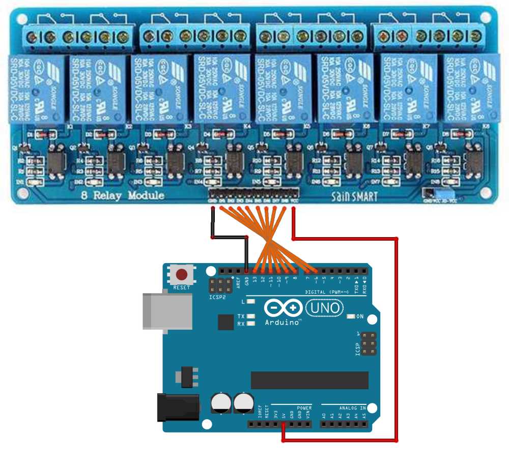
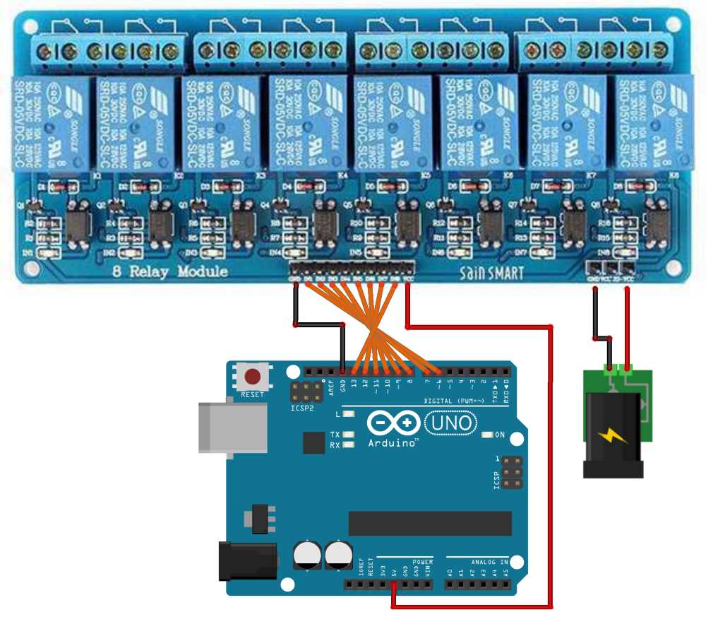
We connect the Arduino to the Logic Terminal pins (GND, IN1…8, Vcc). The GND and Vcc pin are routed to the Power Terminal as well. By connecting a jumper (short) between Vcc and JD-Vcc, the Arduino +5Vdc voltage will now power the relay coils. If however the Arduino has other duties to perform, or if the coils introduce voltage spikes on the power rail, we can use a separate power supply. This external power supply simply needs to be +5Vdc >200mA to drive all 8 relay coils. Simply remove the jumper and connect the external power supply to the GND and JD-Vcc pins of the Power Terminal.
Schematic
Circuit (Jumper enabled)
Circuit (Jumper disabled)
Code
/* SainSmart 8 Channel DC 5V Relay Module */

int in1= 6;
int in2= 7;
int in3= 8;
int in4= 9;
int in5= 10;
int in6= 11;
int in7= 12;
int in8= 13;

void setup() {
  // put your setup code here, to run once:

  //set pins as output
  pinMode(in1, OUTPUT);
  pinMode(in2, OUTPUT);
  pinMode(in3, OUTPUT);
  pinMode(in4, OUTPUT);
  pinMode(in5, OUTPUT);
  pinMode(in6, OUTPUT);
  pinMode(in7, OUTPUT);
  pinMode(in8, OUTPUT);

}

void loop() {
  // put your main code here, to run repeatedly:

  digitalWrite(in1, HIGH);
  delay(500);
  digitalWrite(in2, HIGH);
  delay(500);
  digitalWrite(in3, HIGH);
  delay(500);
  digitalWrite(in4, HIGH);
  delay(500);
  digitalWrite(in5, HIGH);
  delay(500);
  digitalWrite(in6, HIGH);
  delay(500);
  digitalWrite(in7, HIGH);
  delay(500);
  digitalWrite(in8, HIGH);
  delay(3000);

  digitalWrite(in1, LOW);
  delay(500);
  digitalWrite(in2, LOW);
  delay(500);
  digitalWrite(in3, LOW);
  delay(500);
  digitalWrite(in4, LOW);
  delay(500);
  digitalWrite(in5, LOW);
  delay(500);
  digitalWrite(in6, LOW);
  delay(500);
  digitalWrite(in7, LOW);
  delay(500);
  digitalWrite(in8, LOW);
  delay(3000);

}