
Arduino + Mains power (433MHz TX + Safe)
Description
Do NOT interface an Arduino board with any mains power cabling, components, etc. However, rather than telling you what you can’t do, the polite thing to do would be to at least provide you with a solution how you can achieve the desired result in a safe way.
Remote Control Mains Operated Switch
In Australia you can buy these “click on, click off” remote control mains operated switch units. They come with a small radiofrequency (RF) remote control and a number of switch units. This particular model is a PowerTran A0342.
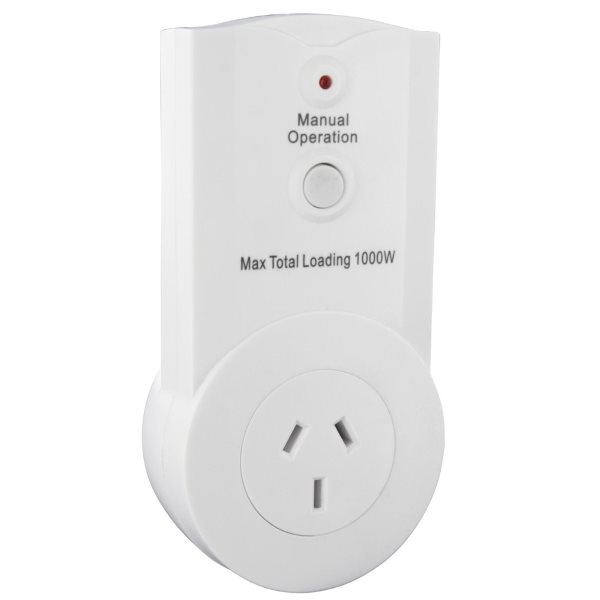
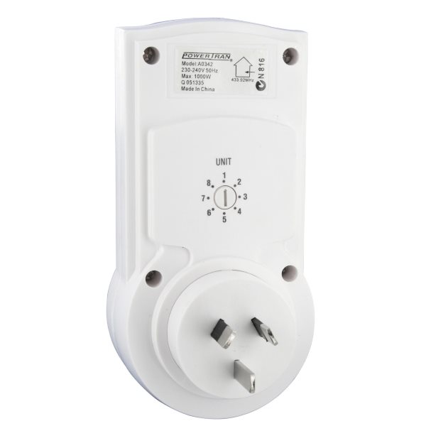
The switch modules are placed in between a wall power outlet and the device you would normally plug into the wall power outlet. The switch modules can handle devices consuming up to 1000W. You can use them to turn on or turn off any power outlet in your house to switch on outside lights , lights inside your home, the garden sprinklers (solenoid valve), etc. The RF remote control unit supports up to 8 switch unit channels. You can have multiple switch units listen on a single channel.
433MHz
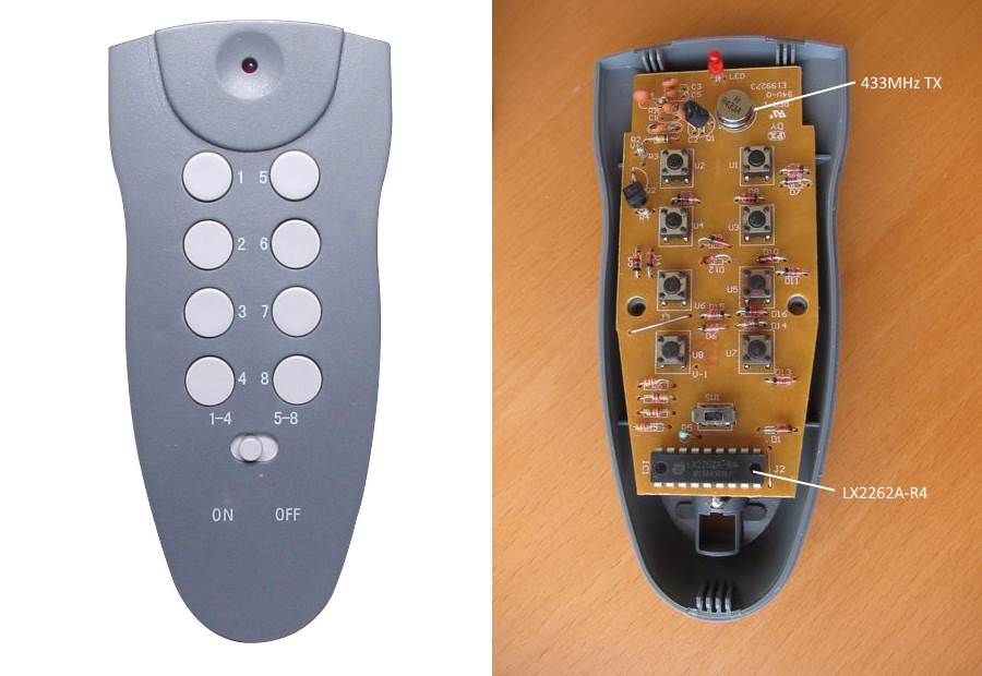
The 433MHz band is popular for all kinds of wireless communication gizmos like garage door openers, smart meters and -in this case- remote control power outlets. The RF remote control unit contains a logic chip LX2262A, some momentary pushbuttons, a LED and a transmitter chip. It is reasonable to assume the switch modules contain a receiver chip and a logic chip to decode the data it receives, combined with a relay.
Our goal is to analyze the data sent by the RF remote control and see if we can make the Arduino send the same signals instead. For this you would need an oscilloscope and a measuring probe to record the signal feeding into the transmit chip. Alternatively you could build a 433MHz receiver using an Arduino and a 433MHz RX module and log data to the serial port. Or you can simply read the datasheet for the LX2262A chip.
Tri-State Protocol
The LX2262A uses the same Tri-State protocol as the popular PT2262 chip. Instead of sending just “One” and “Zero”, the chip uses a specific pulse for each instead. This helps avoid situations where an accidental voltage spike is picked up by the receiver as a “One” or “Zero”. The protocol also supports a “Fault” pulse to indicate an error and a “Sync” pulse to indicate the end of a transmission. Any noise picked up by the receiver will result in the Sync pulse not being received correctly thus avoiding false positives at the receiver end. All this combined offers some rudimentary flow control to ensure data packets are received correctly. Data is however not re-transmitted; if the receiver does not pickup a proper signal, you simply have to press the button on the RF remote control unit a second time to try again.
"0" Bit => 1/8 cycles on, 3/8 cycles off, 1/8 cycles on, 3/8 cycles off   -...-...
"1" Bit => 3/8 cycles on, 1/8 cycles off, 3/8 cycles on, 1/8 cycles off   ---.---.
"F" Bit => 1/8 cycles on, 3/8 cycles off, 3/8 cycles on, 1/8 cycles off   -...---.
"S" Bit => 1/8 cycles on, 31/8 cycles off -...............................
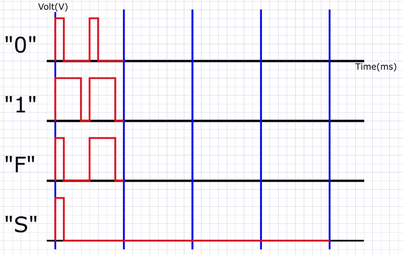
The duration of a “1”, “0” or “F” pulse is approximately 230 us (microseconds) which equals to 4.348 kHz (kiloHertz). Note that this is nowhere near 433MHz. The 4kHz signal is amplitude modulated on top of a 433MHz carrier wave. As an Arduino runs on 16MHz it can easily generate a 4kHz data signal. The 433MHz TX transmitter will take care of the carrier wave generation and amplitude modulation.
If we start pressing buttons on the RF remote control, the following Tri-State pulse sequences are sent:
Address Bits: 8
Channel 1 = 01110000
Channel 2 = 00110000
Channel 3 = 01010000
Channel 4 = 00010000
Channel 5 = 01100000
Channel 6 = 00100000
Channel 7 = 01000000
Channel 8 = 00000000

Data Bits: 4
Turn On  = 1000
Turn Off = 0000

Note: The "1" and "0" symbols in the above list are Tri-State protocol ones and zeroes(!)
So to turn on a switch module listening on channel 5 we would need to send the following Tri-State pulse sequence:
01100000 1000 S
Now let’s see if we can program an Arduino to generate these pulse sequences for us instead of having to use the RF remote control unit.
Hardware Required
- Arduino Uno board
- 433Mhz TX transmitter
- Hookup wire
You can buy 433MHZ transmitters (TX) and receivers (RX) very cheap on the internet.
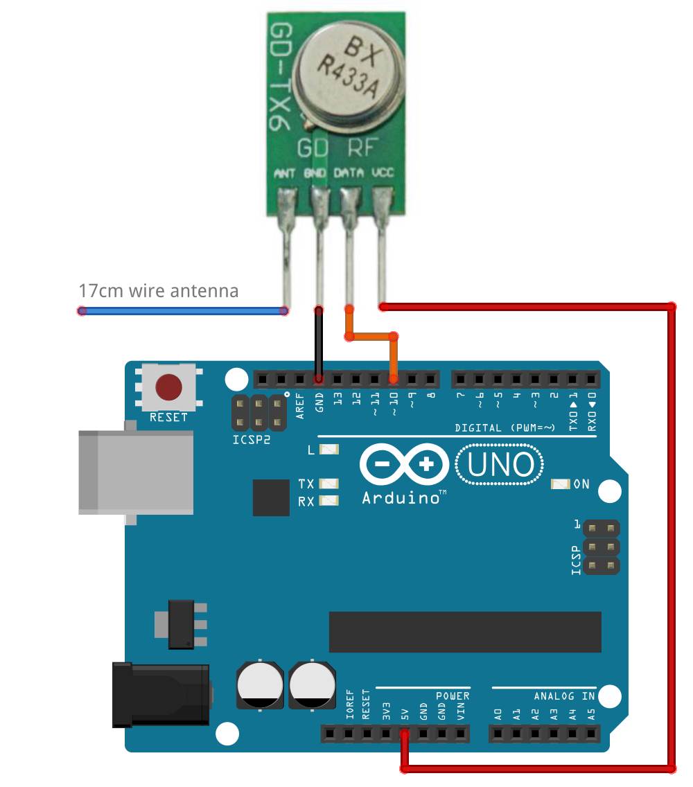
Pinout
ANT – Antenna
GND – Ground
DATA – Data
Vcc – Power
It is recommended so solder a 17cm wire to the ANT pin of the transmitter.
Circuit
Code
This code requires the RCswitch library which can be found here: https://github.com/sui77/rc-switch
The RCswitch library will translate our “1” and “0” and “S” symbols into proper Tri-State pulses. The RCswitch library already recognizes a number of specific brands of remote control mains operated switch products. If your device is not supported you will need to manually set the PulseLength and send raw codes using the RCSwitch::send() or RCSwitch::sendTriState() methods, as shown below.
You can simply download the RCswitch library as a ZIP file and import it into your Arduino software using the menu. We can then test and upload the following code to the Arduino board:
#include <RCSwitch.h>
RCSwitch mySwitch = RCSwitch();
void setup() {
  mySwitch.enableTransmit(10);  // Using Pin #10
  mySwitch.setPulseLength(230); // 230 microseconds
}
void loop() {
  mySwitch.sendTriState("011100001000S"); // #1 ON
  mySwitch.sendTriState("001100001000S"); // #2 ON
  mySwitch.sendTriState("010100001000S"); // #3 ON
  mySwitch.sendTriState("000100001000S"); // #4 ON
  mySwitch.sendTriState("011000001000S"); // #5 ON
  mySwitch.sendTriState("001000001000S"); // #6 ON
  mySwitch.sendTriState("010000001000S"); // #7 ON
  mySwitch.sendTriState("000000001000S"); // #8 ON
  delay(1000);
  mySwitch.sendTriState("011100000000S"); // #1 OFF
  mySwitch.sendTriState("001100000000S"); // #2 OFF
  mySwitch.sendTriState("010100000000S"); // #3 OFF
  mySwitch.sendTriState("000100000000S"); // #4 OFF
  mySwitch.sendTriState("011000000000S"); // #5 OFF
  mySwitch.sendTriState("001000000000S"); // #6 OFF
  mySwitch.sendTriState("010000000000S"); // #7 OFF
  mySwitch.sendTriState("000000000000S"); // #8 OFF
  delay(1000);
}
Note the Most Significant Bit (MSB) of the data payload is transmitted first e.g. tristate pulse trains are sent in the order of starting from the left hand side first towards the right hand side last. The Sync pulse ‘S’ to mark the end of a transmission is transmitted last.
If you plug-in the switch modules and set them to different channels, you should see them turn on and off once a second. You can modify the code from here or use it in already existing code as you see fit.