
Shaders
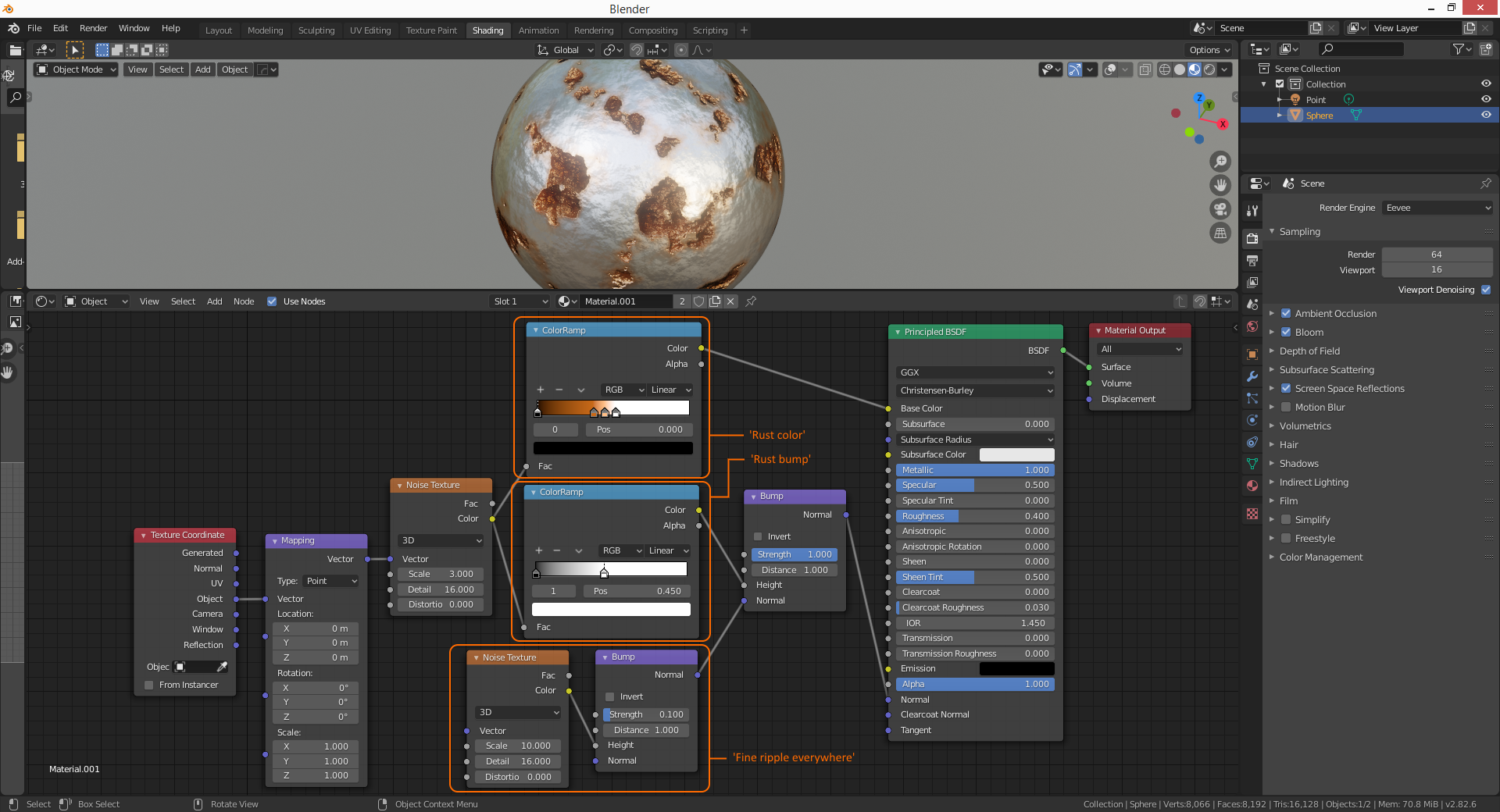
Understanding of the following viewport render settings is key:
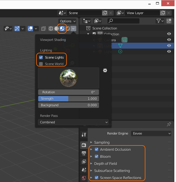
For shaders using transparency, the material blend mode needs to be changed from Opaque to Alpha Blend:

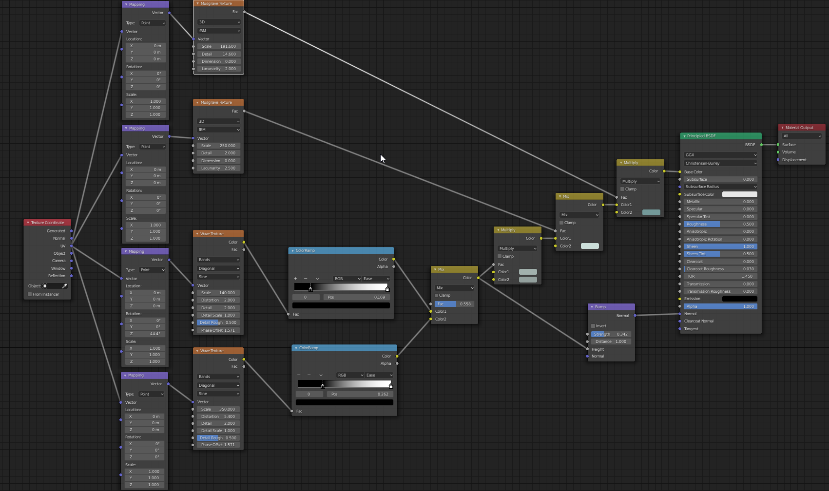
Blue dots = Vector coordinates
Yellow dots = RGBA color
Gray dot = Value between 0.0 (black) and 1.0 (white).


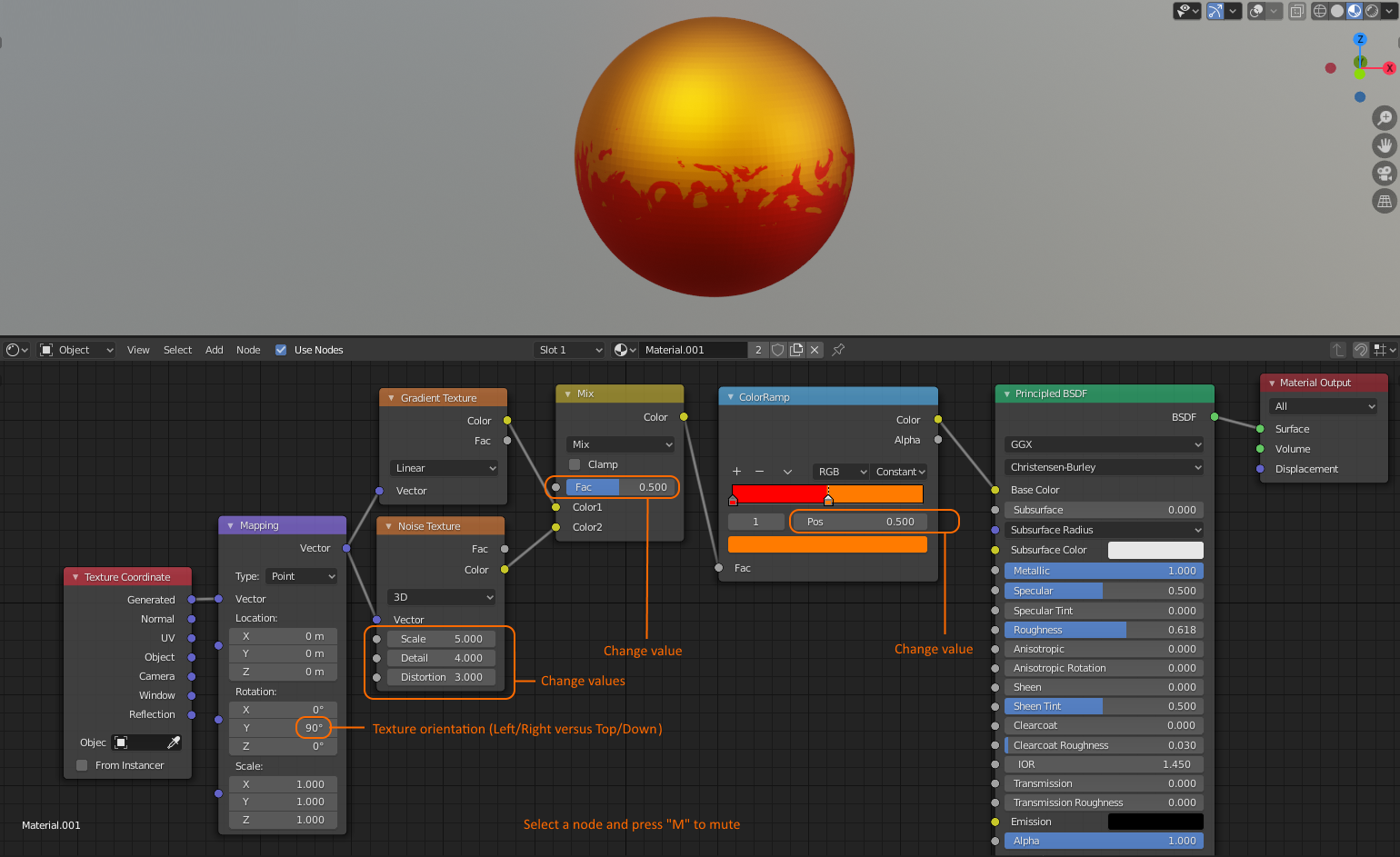
shader0005.blend
The Bump node is resource intensive in this example and can be muted [M]
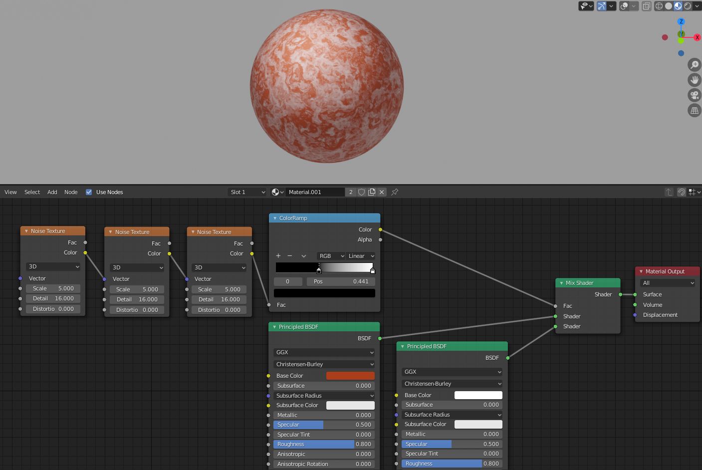
shader0007.blend
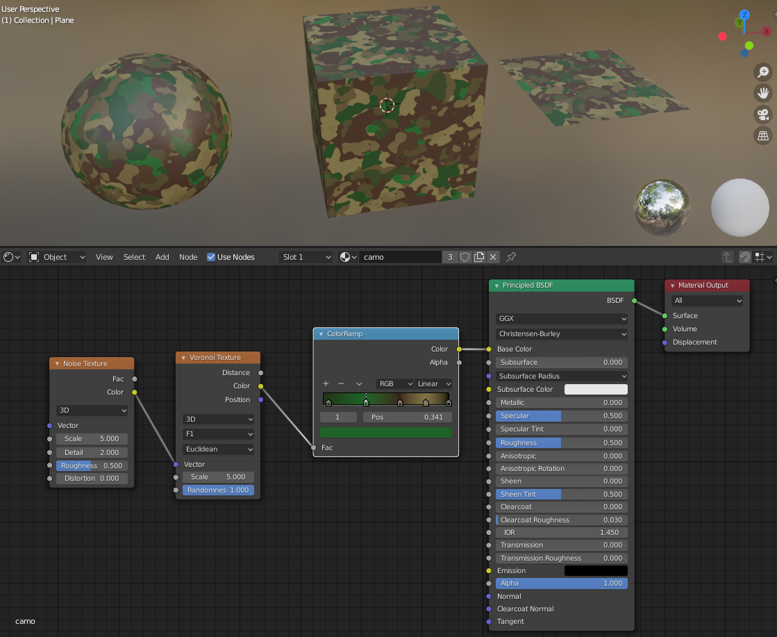
Explains how to map different colors to different areas of a texture using a ColorRamp.
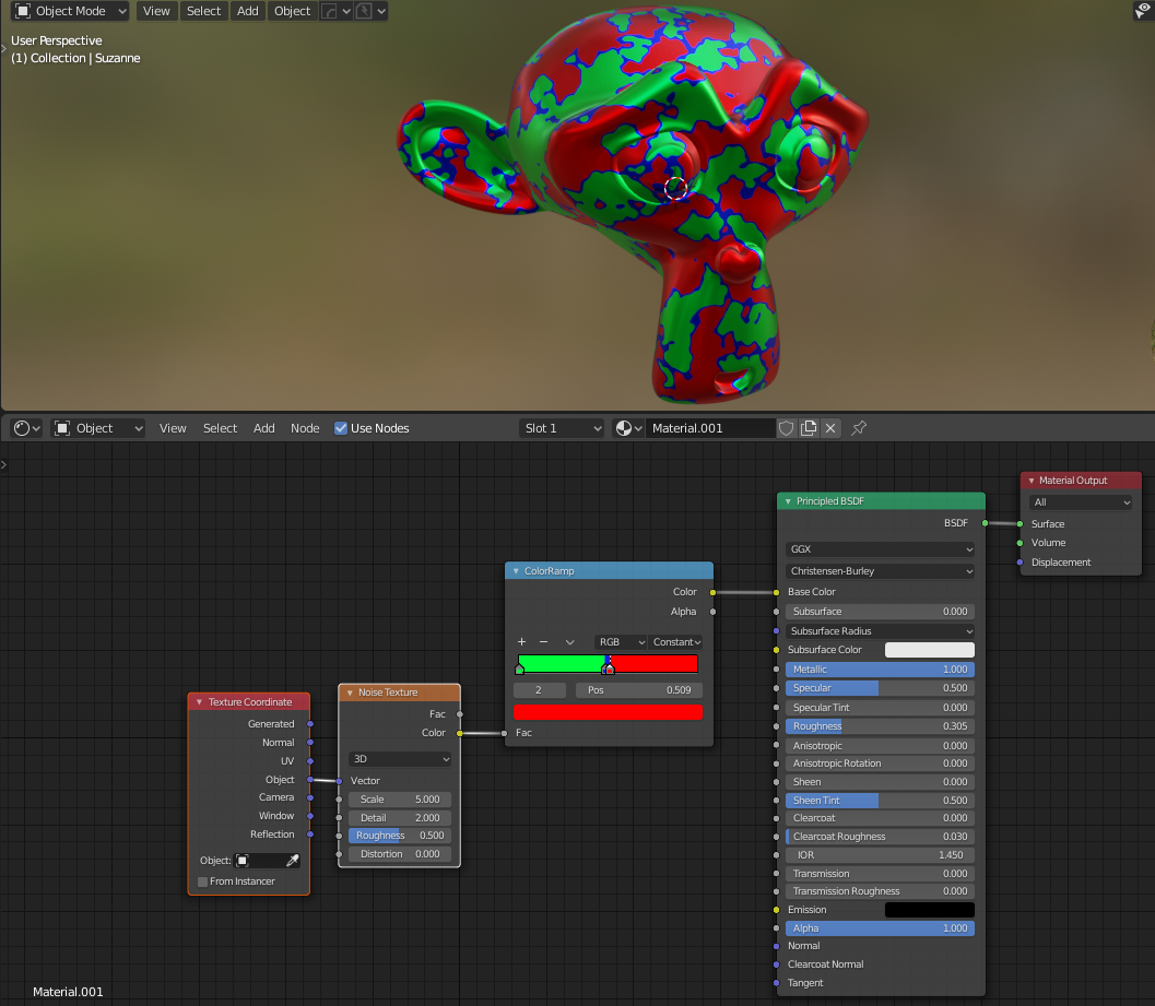
But what if each color needs to be a separate material, like red is transparent and blue is an emission to create an animated texture that eats a way and dissolves an object, or where both red and green are transparent and only the seam is visible like an ‘electrify’ material shader applied to a bounding box cube or sphere surrounding another object.
We start by using MixRGB nodes.
Noise texture has gray colors from black (0.0) to white (1.0)
MixRGB with “Factor = 0.495” puts transition between blue and green at 49.5% gray (seam 2).
MixRGB with “Factor = 0.5” puts transition between {previous} and red at 50% gray of noise texture (seam 1).
This leaves a small band of blue sitting between the 49.5% and 50% seams.
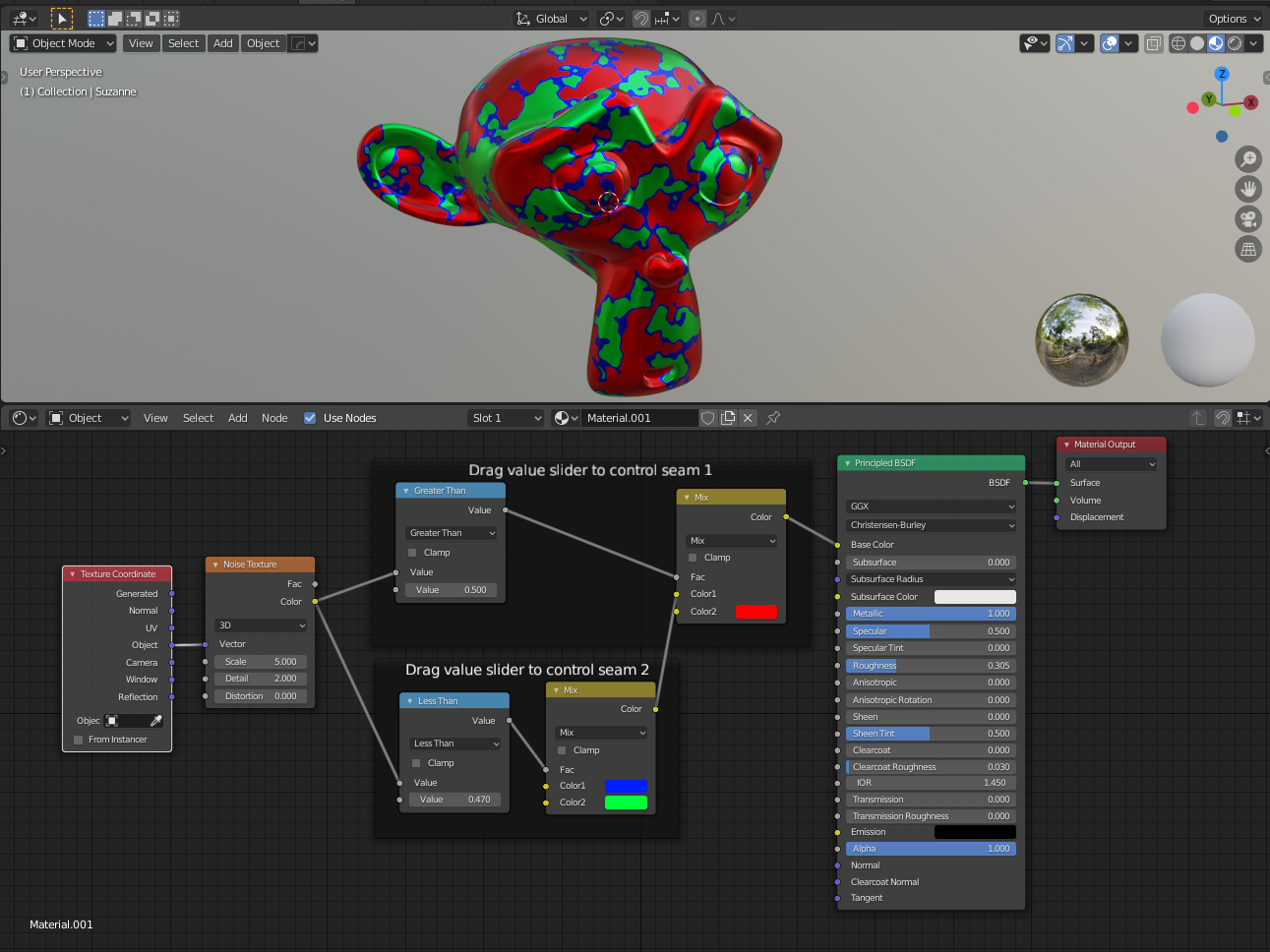
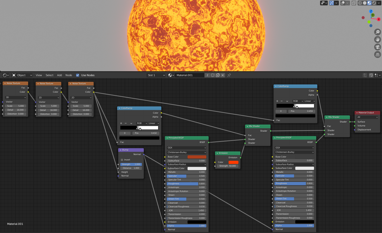
Instead of MixRGB nodes you can switch to MixShader nodes and use different materials to create an (animated) dissolving material or electrify material.
shader0008.blend
(Eevee)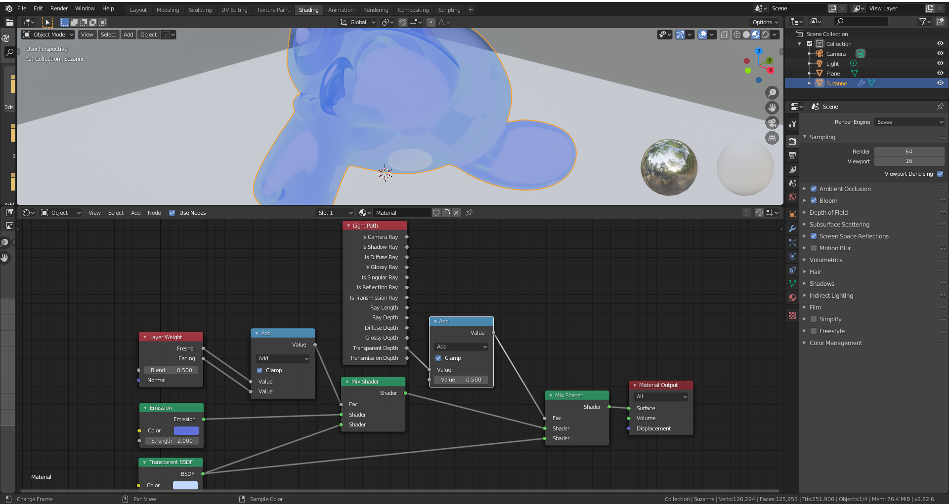
shader0009.blend
‘Wireframe node’ currently only works in Cycles, not Eevee (Blender 2.82 alpha)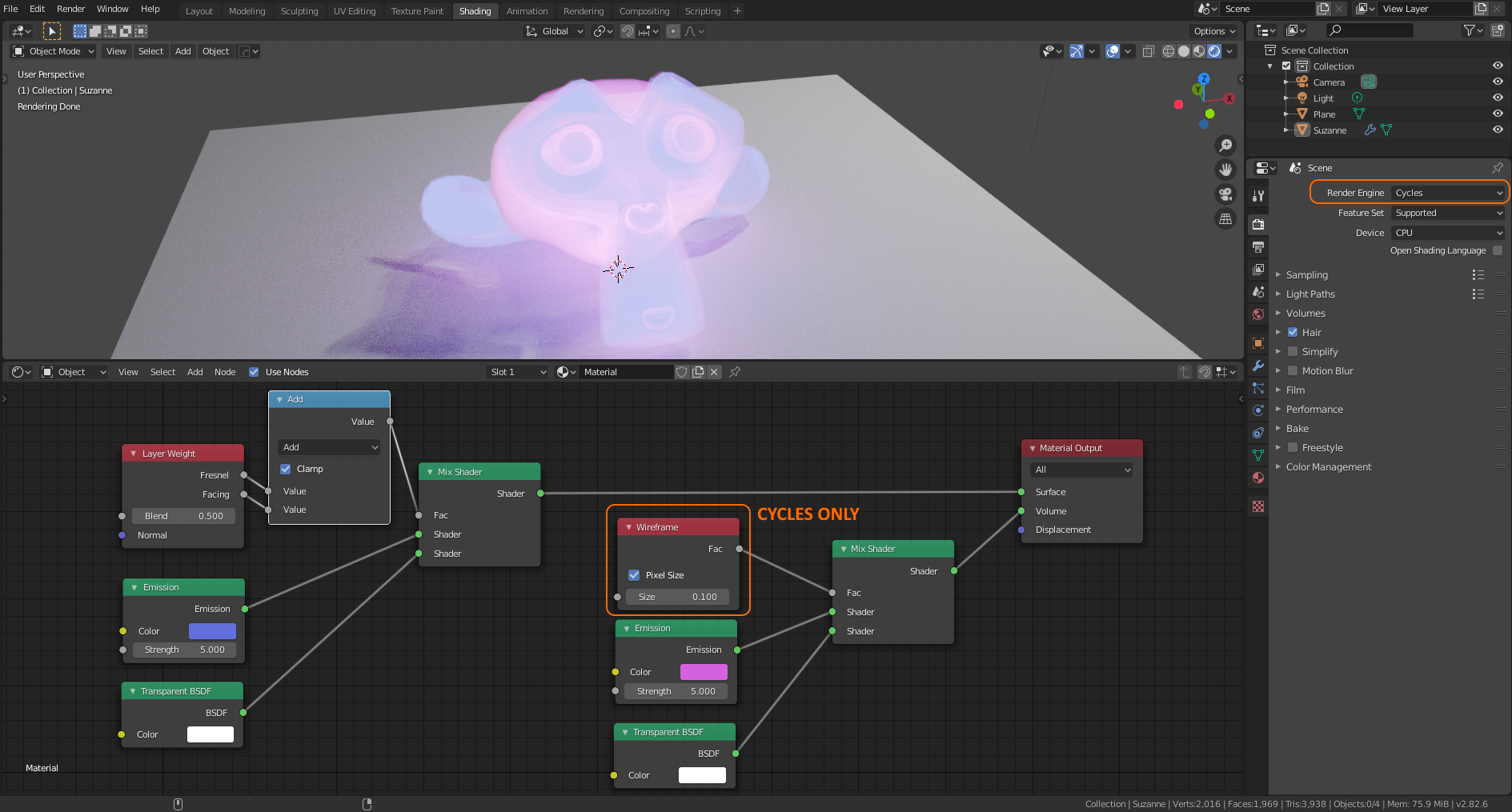
shader0010.blend
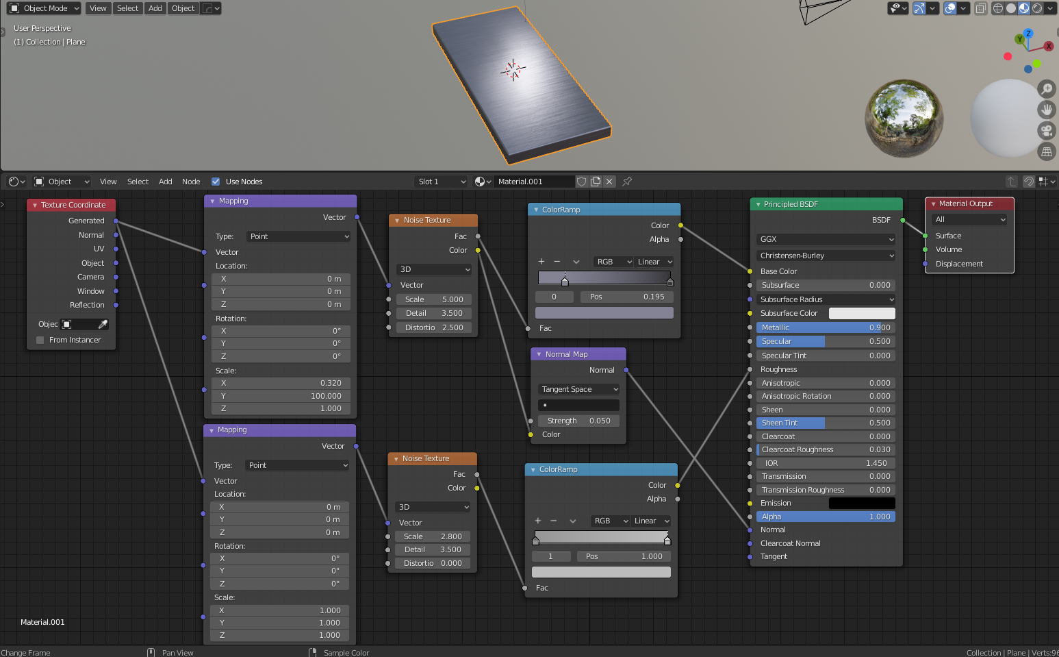
Brushed metal. Roughness is controlled by RGB of color ramp (03 – 0.5)
shader0011.blend
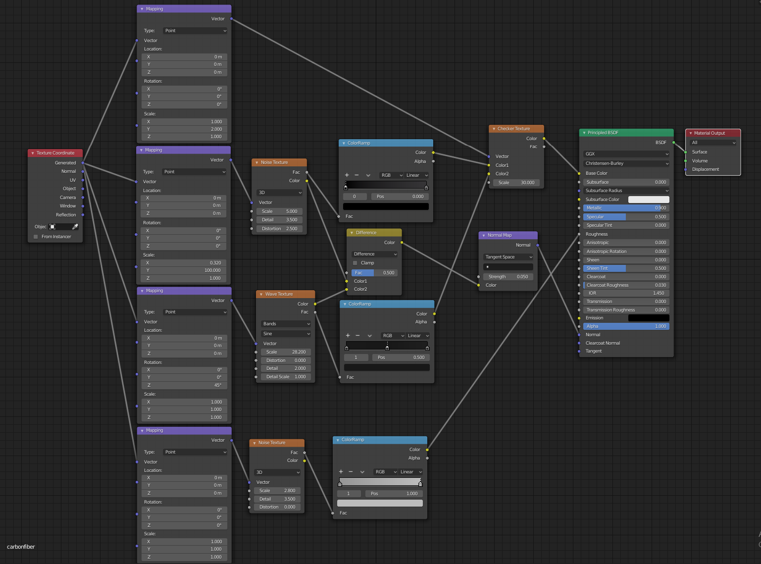
Carbon fiber comes in a checker weave or herringbone weave pattern. I am using a checker with wave and noise.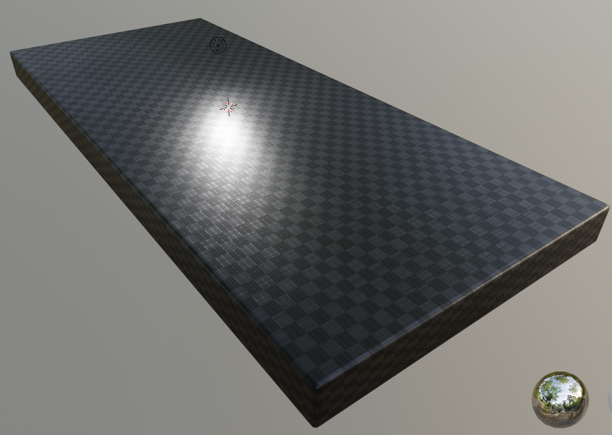
shader0012.blend
car paint. looks really good here, but is a bit dull on flat surfaces.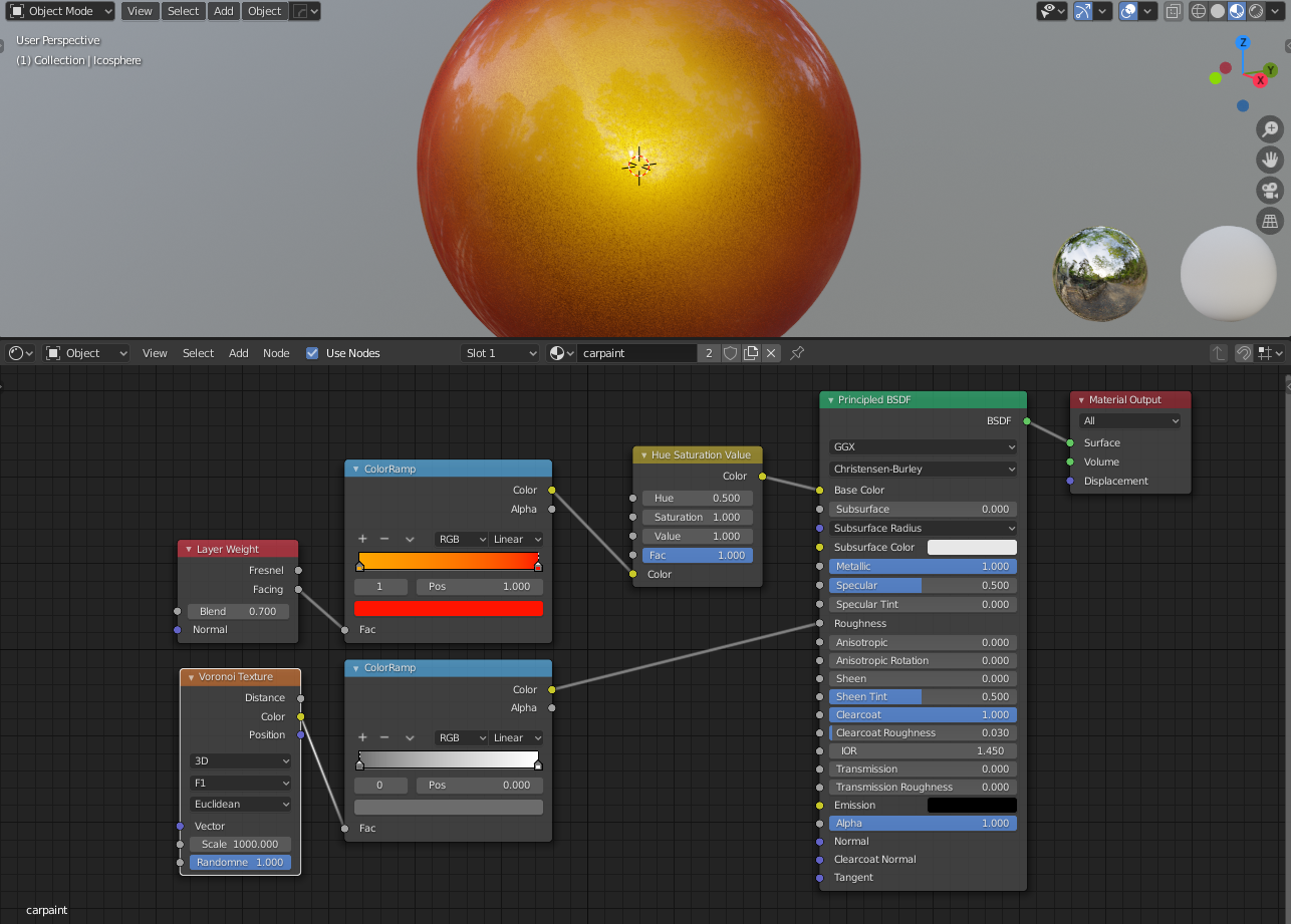
shader0013.blend
1 material for all emitters to have them blink randomly.
shader0014.blend
Looks great even if not UV unwrapped. Bit heavy on resources due to the double stacked bump nodes.
shader0015.blend
Leather
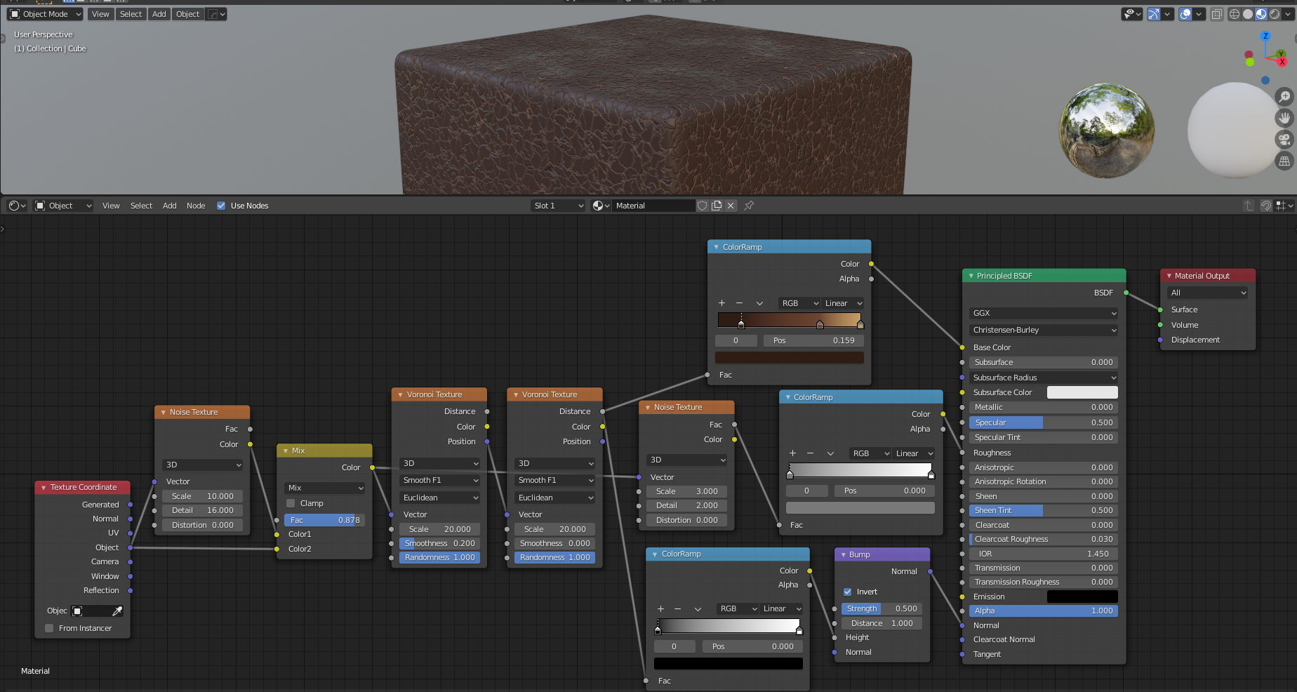
shader0016.blend
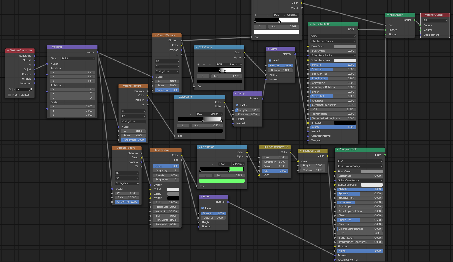
Worn and scratched paint. Bit heavy.

shader017.blend
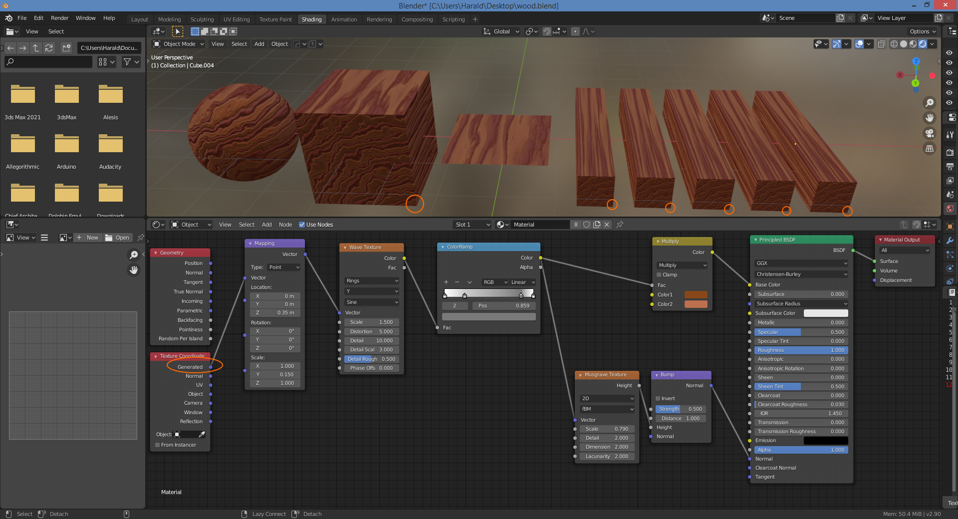
Wood grain material suitable for individual planks or beams. Not intended for floors.
Not reflective. You can decrease Roughness for varnished timber.
Wave Texture > Y controls direction of grain. If you change this to X, you have to change Mapping node scaling from Y to X as well to keep same pattern.
Mapping node Z location controls center of wood rings location. This is dependent on thickness of your object.
Geometry > Generated = Each plank will be identical as texture is placed relative to each object’s local origin. Note how the wood grain rings are visible but originate from the lower right corner of the object however.
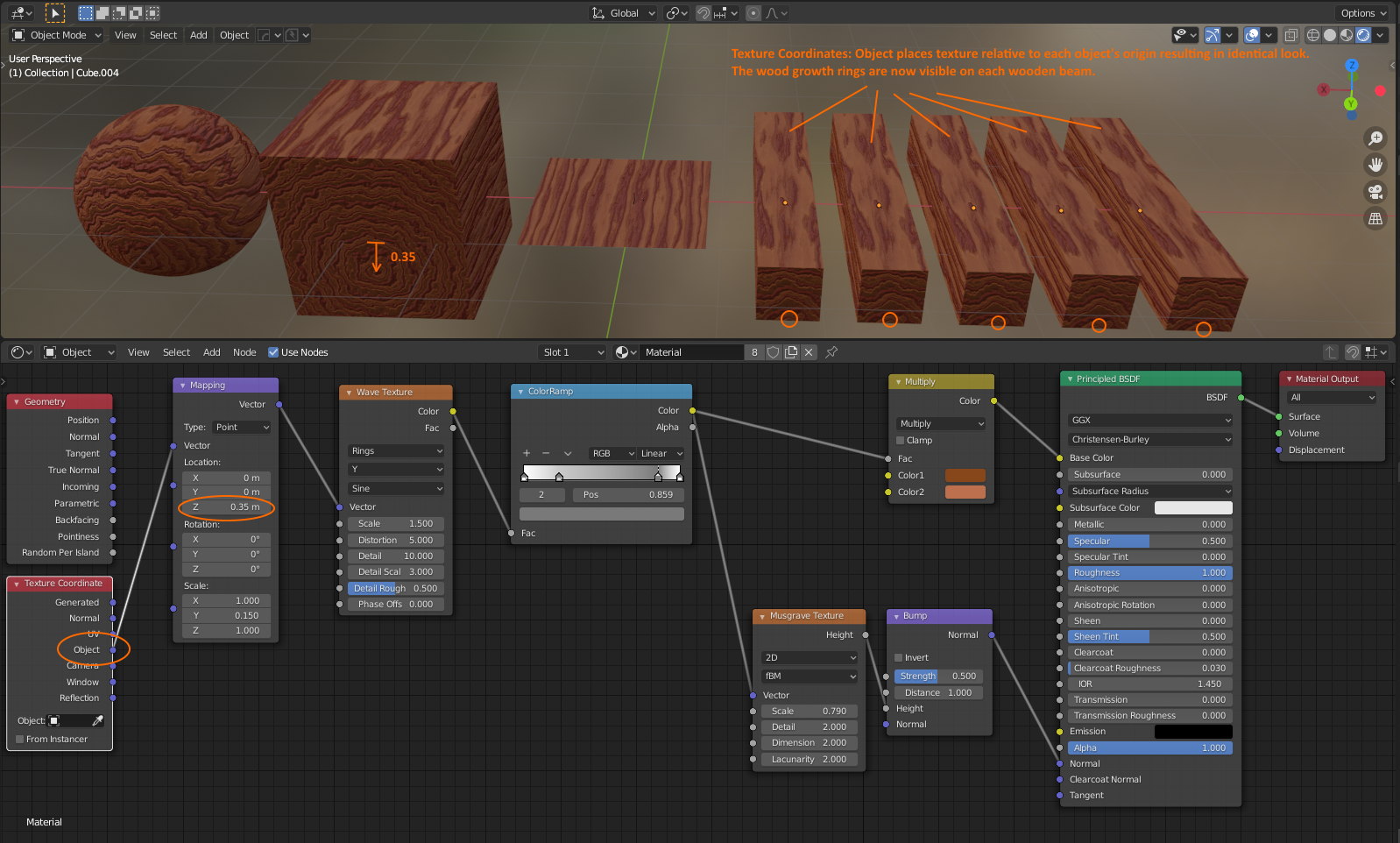
Geometry > Object = Each plank will be identical as texture is placed relative to each object’s (local origin). Note how the wood grain rings are now visible and originate from the center of the object. Mapping node Z location is used to move the center of the wood growth ring to the bottom of the beams/planks. This is dependent on the thickness of your beams/planks.
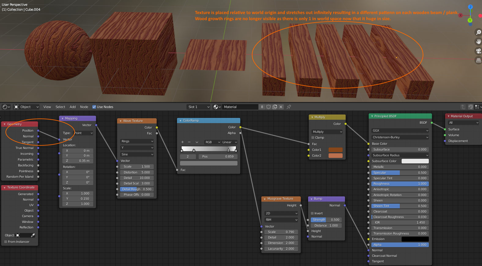
Geometry > Position = World origin is used. The texture is placed in world space independent of the object.
Note each wooden plank now has a different pattern. There is no repetition. Object origin is not used. Wood growth rings are no longer visible however as there is now only 1 growth ring that is relative to the world origin and huge in size.
shader0017.blend
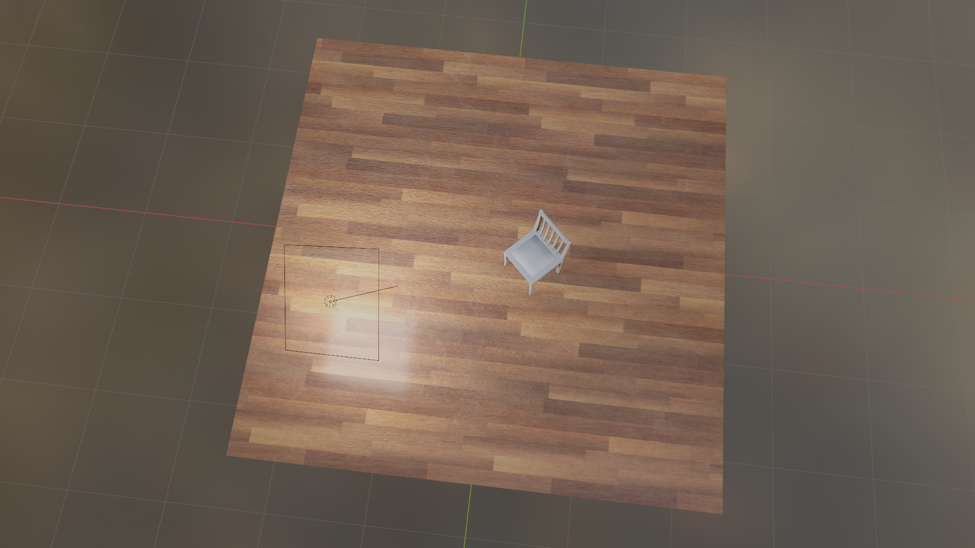
Wooden flooring
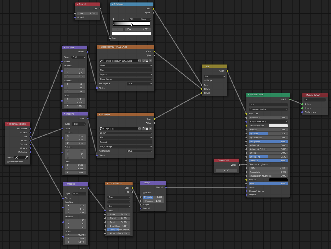
The camera is always inside the room when looking at a floor, so the camera is never extremely zoomed in or zoomed out and should pick up photographic image texture details nicely. I decided to use a photographic 2K (2048 x 2048) seamless image texture for various reasons:
– you can swap it for a different type of wood easily.
– photo-realistic details.
– all other material properties (bump, reflection, specular) are related to the varnish and not the wood. This means all other material properties can be easily created independently.
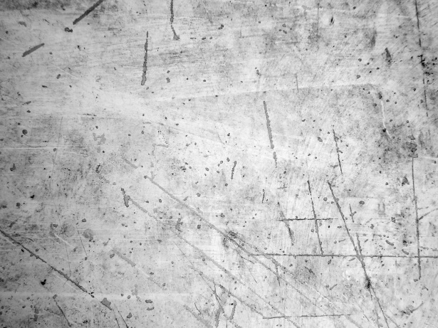
I decided to use a 1K (1028 x 1028) resolution black and white photograph for wiping marks instead of a procedural generated pattern for various reasons:
– wiping marks are blurred and broad strokes, requiring a lower resolution photo.
– wiping marks are not related to the color of the material and can just be a black and white map mixed in with the color.
– you can easily find different seamless tiled wiping marks photos on the internet.
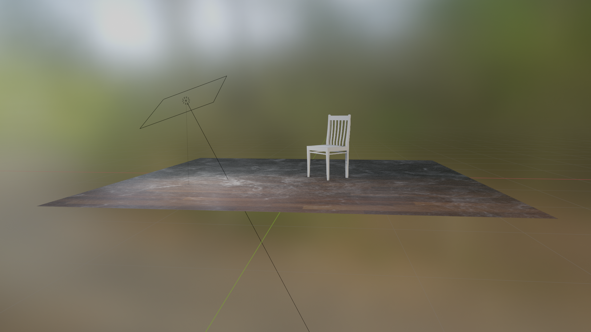
A Fresnel node controls the MixRGB Factor so the wiping marks are not visible when looking top down, but start to appear when glancing over the surface side on.
To avoid the material looking like linoleum flooring you would need to work on giving depth to the seams between planks. You can do this by either switching to a more procedural workflow using a brick texture node mixed into multiple slots (diffuse, bump, reflection, specular) or by switching to a photoreal material by using a set of carefully crafted seamless images for (diffuse, bump, reflection, specular) slots of the material.
I think the mix of a 2K seamless photo for color combined with a 1K seamless photo for smudges combined with procedural bump works well and is lightweight and flexible.
Top view
Glancing over surface view
shader0018.blend
Camouflage pattern
shader0019.blend
Lava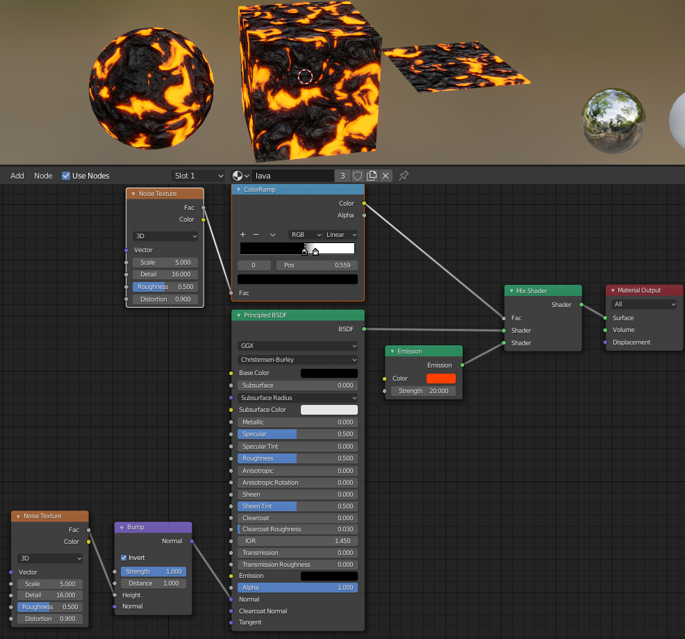
shader0020.blend
asphalt road surface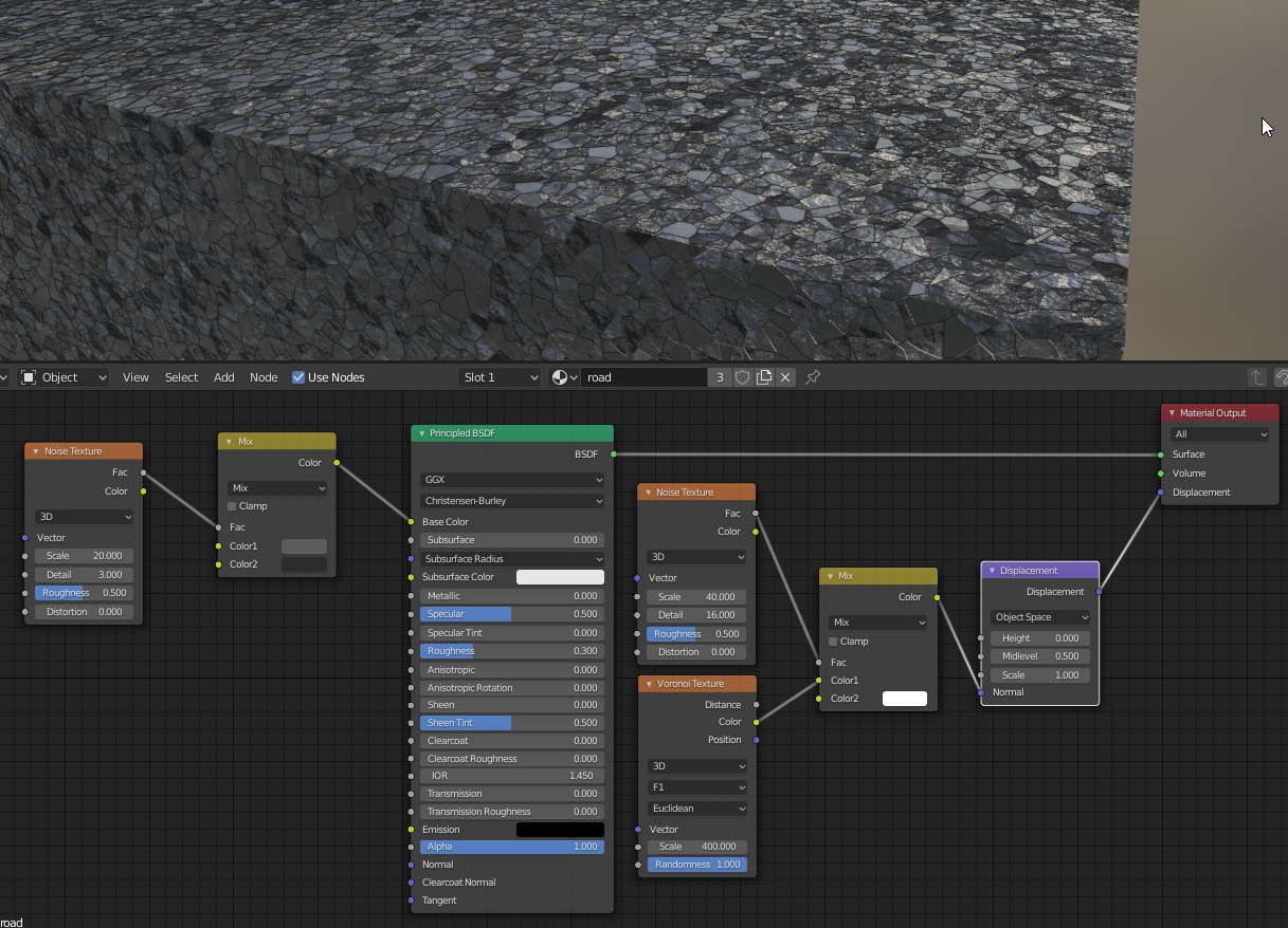
shader0021.blend
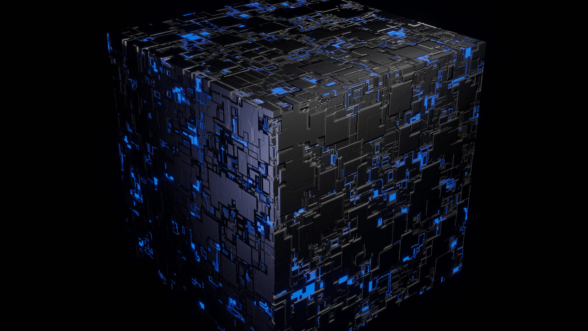
hull plating
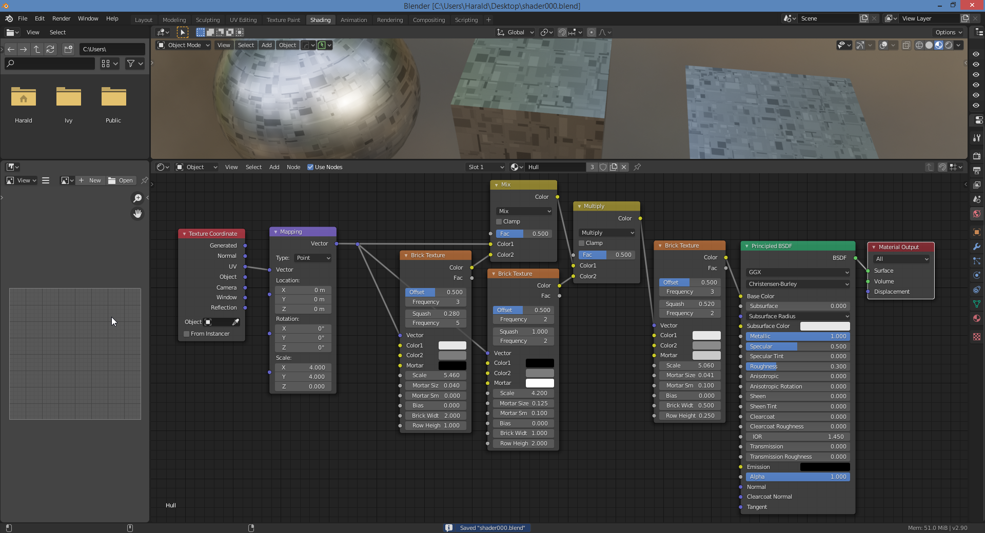
shader0022.blend
Jade
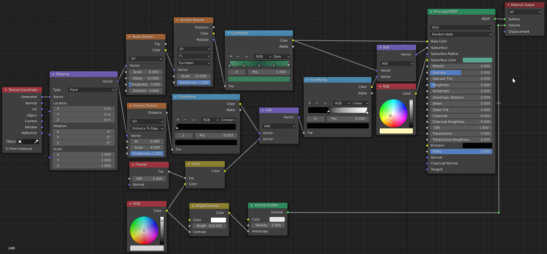
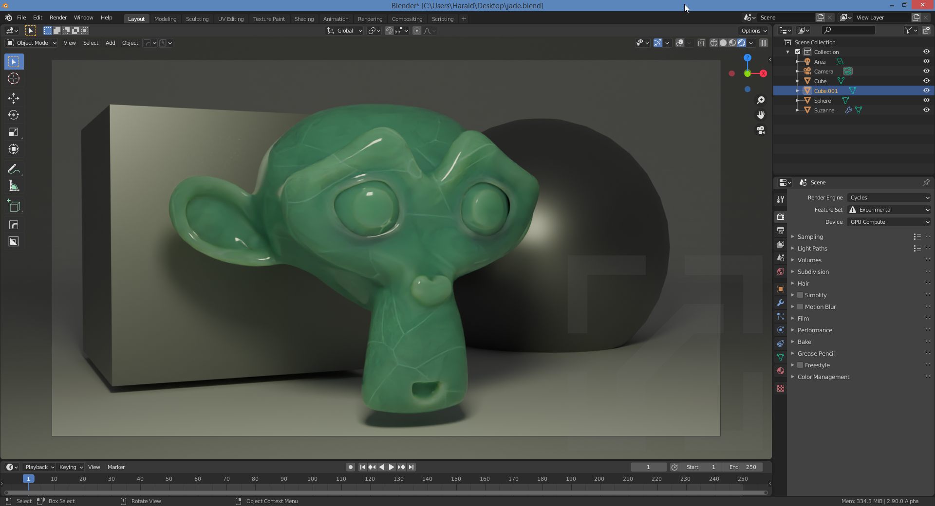
shader0023.blend
fabric
shader0024.blend
dots
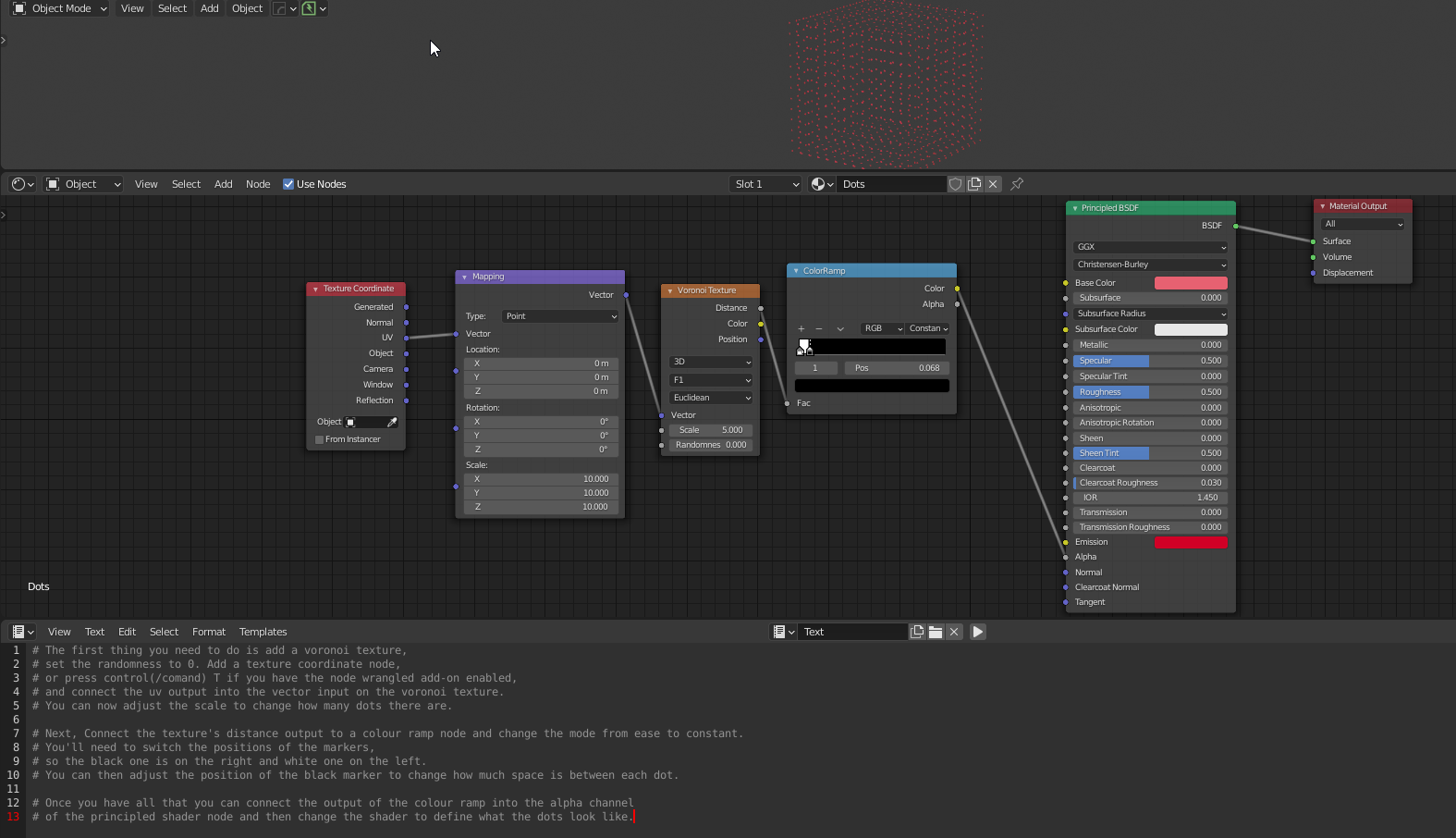
Controlling a gray input slot (0.0 to 0.1) value.
To set Roughness between 0.3 and 0.5, connect a ColorRamp node and set RGB values for left hand slider all to 0.3 (dark gray) and for right hand slider all to 0.5 (lighter gray).
Viewing nodes
Connect the output of any node to the Material Output node temporarily.
Node Wrangler
CTRL-SHIFT click on a node to ‘see’ it
CTRL-T to connect texture coordinate + mapping nodes instantly.
Procedural Textures Pros/Cons:
- Infinite resolution
- Increased editability
- Can be applied to nearly any model without repetition or resolution issues.
Image Textures Pros/Cons:
- Fast to create download.
- Good results fast
- Large files is always better. You can always resize down but not up.
IMPORTANT: UVW unwrap
Any material that is not homogeneous (anything other than a solid color principled BSDF shader) will show stretching and scaling issues if the object has not properly been UVW unwrapped. Doesn’t matter if it is procedural or (seamless) image tile based; any complex object will need their UV coordinates laid out flat.
Normal maps
http://wiki.polycount.com/wiki/Normal_map
- Only required if bumps in your mesh do not match with bumps in your image textures.
- Only required if you are or can get close-up enough to see bumps and scratches.
You can either:
- Bake
Model hi-poly with real cracks and bumps + setup lighting + bake output as flat 2D diffuse + normal image textures slapped onto a low-poly version of the hi-poly original mesh. - Generate
Use normal map generator (CrazyBump or http://cpetry.github.io/NormalMap-Online/)
Seamless textures
Don’t bother with seamless textures:
https://www.imgonline.com.ua/eng/make-seamless-texture.php
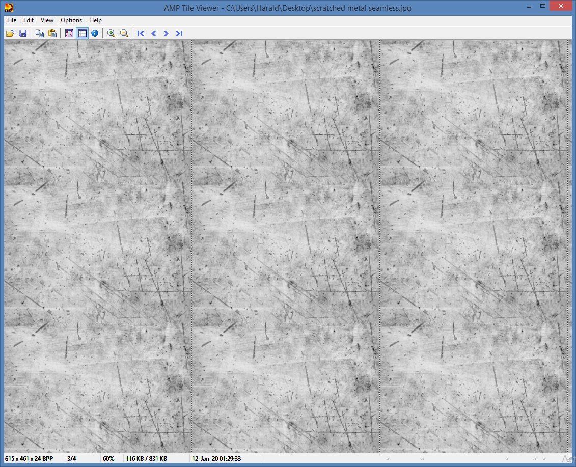
Seamless image textures can work well if photos are larger and are uniform in texture and color (fabrics, wood, brick, foliage, etc.) to minimize repeat artifacts. Seamless image textures offer more flexibility for when viewing distance increases (UV tiling) but lack detail compared to a non-seamless image textures. Procedural is more flexible still (scaling + nodes editing) but lacks photorealism when close-up.
Transparency
Transparency in game engines can be problematic.
PNG is so feature rich, different programs may save PNG slightly differently and corrupt alpha channel data.
TGA is dumb and therefore preferred. Requires a Windows viewer like XnShell to view.