MPCNC part 6
MPCNC Marlin config
This is where I keep my current MPCNC config in case I have to reflash it:
Single endstops software enabled (G53 Xpos Ypos only) – Marlin_software_endstops_enabled+G54fix.zip
Single endstops software disabled – Marlin_software_endstops_disabled.zip
It is now time to plot the obligatory MPCNC crown test pattern with a pen holder and pen.
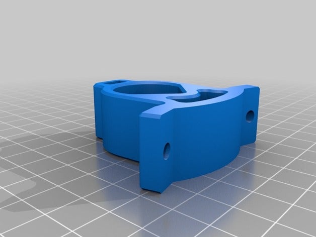
MPCNC Sharpie / Pen holder
https://www.thingiverse.com/thing:3609897
MPCNC_Sharpie_Pen_Tool_Holder.zip
Crown test
https://www.v1engineering.com/wp-content/uploads/2015/09/Test-Crown-12mms.gcode


This is the actual result of the very first time the machine was used to plot a file. I had to restart the operation as the pen tip was a fraction too close to the surface and started dragging. The second attempt completed successfully.
GRBL
It is worth noting that at this point I realized GRBL would be better than Marlin. GRBL returns positional statements whilst doing curves (which is important for CNC.js). You can use an Arduino Uno + CNC shield instead of a 3D printer Marlin based logic board to drive steppers using stepstick modules. An additional benefit of Arduino boards is standard header connectors (no JST PH crimping tools or pigtails required.).
So I like my Raspberry Pi CNC.js frontend and Gcode sender, but I am not overly happy with my choice for a 3D printer Marlin board as stepper driver instead of a GRBL board. Such is life, hardware / software to drive CNC is always a bit temperamental…memories of Mach3 vs Mach 4, Warp 9 Ethernet SmoothStepper (ESS), Leadshine DMA860H stepper driver, etc.
Fusion 360
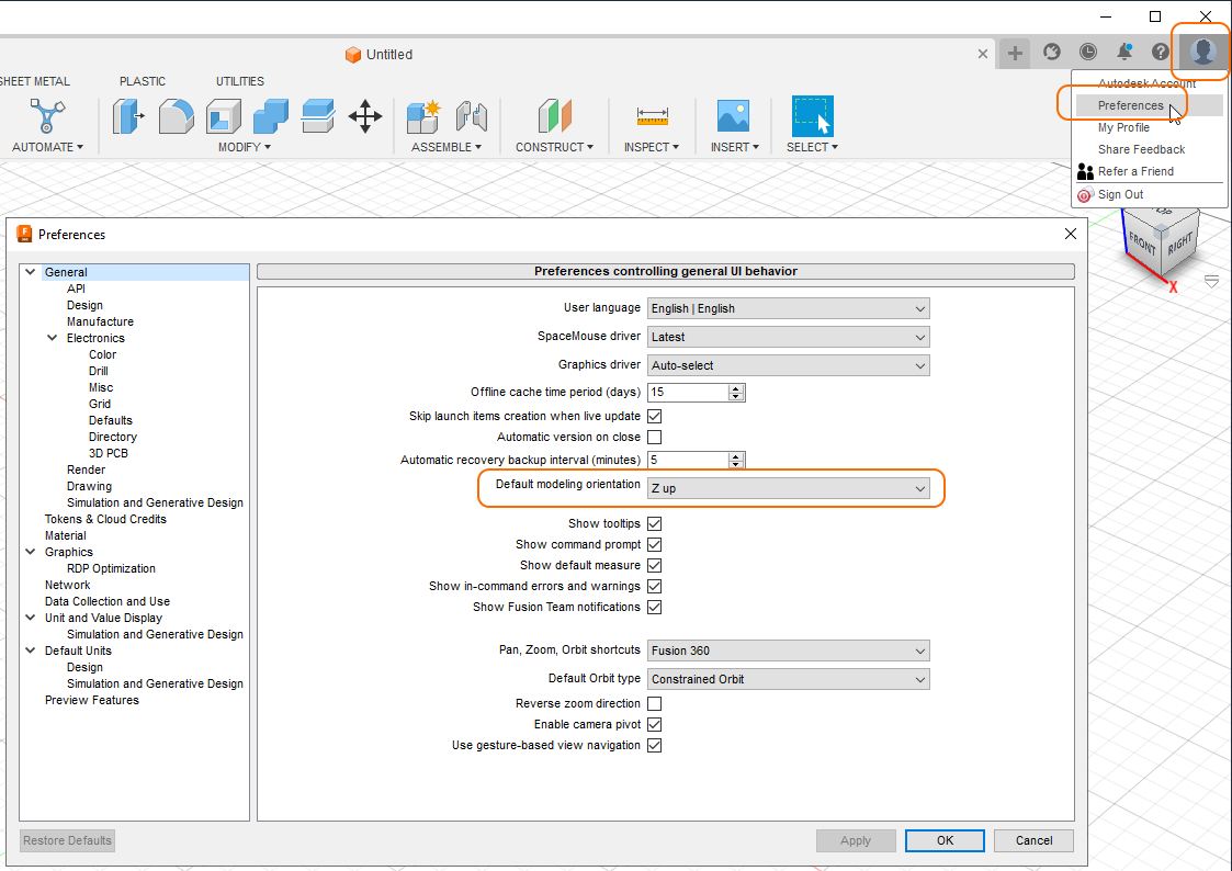
Before we do anything, make sure the coordinate system has Z up [!]
Now we can import a post processor:
https://github.com/guffy1234/mpcnc_posts_processor
Rename *.txt to *.cps
Manufacture > Manage > Post (Processor) Library > Import
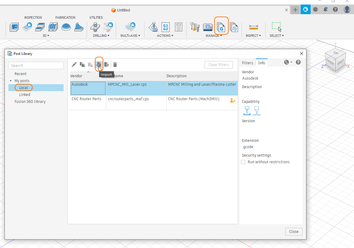
Local post processor files are stored in “C:\Users\…\Appdata\Roaming\Autodesk\Fusion 360 CAM\Posts”
When generating Gcode in Fusion360 select “Setup” and select ‘Use Personal Posts’ from the drop down list.
Spoilboard
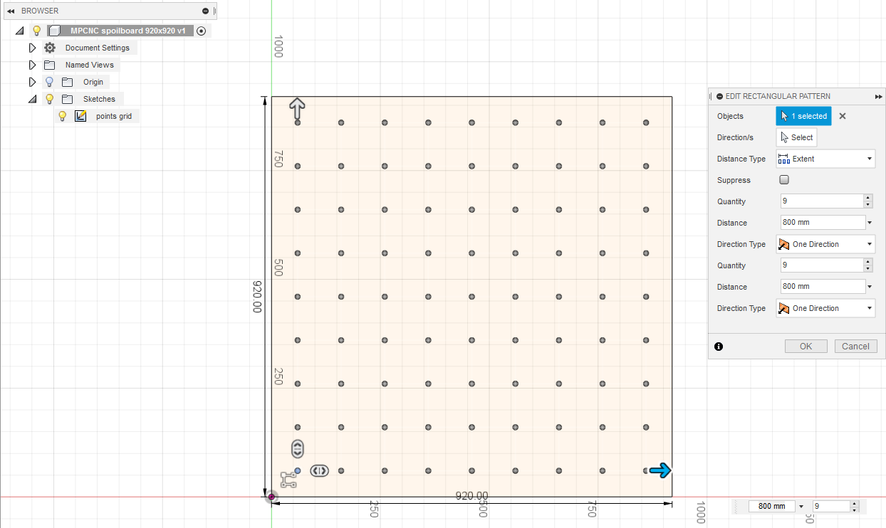
So as a first attempt I created a drill grid for a 920x920mm spoilboard consisting of a 9 x 9 points grid with 100mm spacing and a 60mm edge perimeter:
I then generated a center drilling toolpath and loaded the MPCNC Fusion360 Post processor to generate Gcode:
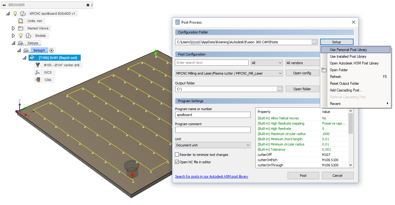
I had to leave some holes out as the machine could not reach.
The resulting code looks as follows: spoilboard.gcode
When I ran the Gcode on the machine I realized my machine does not do absolute negative machine coordinates. I have dual steppers enabled, but not dual endstops (X1min + X2min + Y1min + Y2min) in Config_adv.h. I do however have Xmin and Ymin enabled in Config.h. I do not have limit switches installed as of yet. As soon as you have Xmin and Ymin enabled, the machine will force you to stay within the bed area. This means absolute negative machine coordinates are not allowed; you cannot move beyond the lower left corner. When I power up the machine with the spindle located in the center of the spoilboard, this effectively becomes X0 Y0 Z0 and I cannot move to the left or to the bottom from here as that is considered outside of the bed area.
Instead of going down the rabbit hole of G54 work offset coordinates, I simply disabled the Xmin and Ymin limit switches / endstops feature altogether. I can now start anywhere on the board.
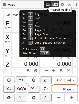
CNC.js keypad jogging
In order to use CNC.js keypad jogging you will need to first minimize the Console Widget as otherwise the Console Widget will hijack all keyboard input. Then, click on the keyboard symbol in the Axes Widget to enable keypad jogging. Make sure to set the step size to a safe value before pressing Arrow Keys or Page Up / Page Down.: