Electrical
Disclaimer
Always contact a certified electrician for mains powered electrical wiring.
Information may contain errors. Information may be incomplete. Information is provided for my own personal education only. No warranty. No guarantees.
Earth vs Neutral
Ground or (protective) earth in a mains AC power electrical wiring system is a conductor that provides a low-impedance path to the earth to prevent hazardous voltages from appearing on equipment.
Neutral is a circuit conductor that normally completes the circuit back to the source.
In the TN-S (separate neutral from earth, as opposed to TN-C combined neutral and earth) system, separate neutral and protective earth conductors are installed between the equipment and the source of supply (generator or electric utility transformer). Normal circuit currents flow only in the neutral, and the protective earth conductor bonds all equipment cases to earth to intercept any leakage current due to insulation failure. The neutral conductor is connected to earth only at the building point of supply, but no common path to ground exists for circuit current and the protective conductor.
Source: https://en.wikipedia.org/wiki/Ground_and_neutral
Protective earth is connected to a shared terminal block in both the meter box and any sub boards and connected to the single protective earth ground stake at the point of entry (meter box). Protective earth does not go through any breakers and is wired to each individual GPO directly. Protective earth should not have any current flowing during normal operations. Protective earth is there to ensure it is the preferred path for electrical current to flow to earth and not through you, in case of electrical equipment insulation failure. The overload protection of the circuit breaker will trip in such situations as this is similar to a short circuit. Note the trip curve of a thermal breaker. More on this later.
Multiple Earthed Neutral (MEN)
The protective earth ground stake should be placed where the power comes in from the street. This is to ensure there is a single known return path back to the street transformer in case of equipment insulation failure.
If you run a long cable from a meter box to a shed sub board, the protective earth wire is part of this cable.
If there are concerns the protective earth wire inside a very long cable run is not reliable, you can consider a separate second protective earth ground stake at a shed sub board instead.
Multiple Earthed Neutral (MEN) setup where we have a 2nd protective earth stake at the shed:
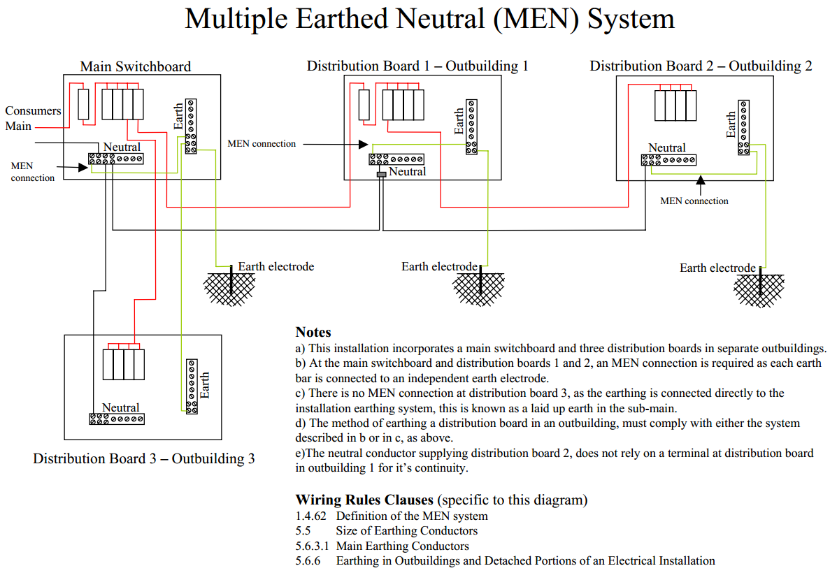
The protective earth wire as part of the feed-in cable to a sub board is preferred over having a multiple earthed neutral system.
Single Wire Earth Return
Single-wire earth return (SWER) or single-wire ground return is a single-wire transmission line which supplies single-phase electric power from an electrical grid to remote areas at low cost. Its distinguishing feature is that the earth (or sometimes a body of water) is used as the return path for the current, to avoid the need for a second wire (or neutral wire) to act as a return path.
Single-wire earth return is principally used for rural electrification, but also finds use for larger isolated loads such as water pumps.
Power is supplied to the SWER line by an isolating transformer of up to 300 kVA. This transformer isolates the grid from ground or earth, and changes the grid voltage (typically 22 or 33 kV line-to-line) to the SWER voltage (typically 12.7 or 19.1 kV line-to-earth).
The SWER line is a single conductor that may stretch for tens or even hundreds of kilometres, with a number of distribution transformers along its length. At each transformer, such as a customer’s premises, current flows from the line, through the primary coil of a step-down isolation transformer, to earth through an earth stake. From the earth stake, the current eventually finds its way back to the main step-up transformer at the head of the line, completing the circuit. SWER is therefore a practical example of a phantom loop.
The secondary winding of the local transformer will supply the customer with either single ended single phase (N-0) or split-phase (N-0-N) power in the region’s standard appliance voltages, with the 0 volt line connected to a safety earth that does not normally carry an operating current.
Source: https://en.wikipedia.org/wiki/Single-wire_earth_return
Residual Current Device (RCD) vs Multiple Circuit Breaker (MCB) vs Residual Current Breaker with Overload protection (RCBO)
An RCD will save your life by ensuring that in case of a current leakage or an imbalance in current, which could result in electrocution, the current is cut off. It is as easy as that. An MCB will save your home from electrical fires by ensuring that the wires are not overheating and that there is no overload on the various electric circuits.
You need to ensure that you have both of them in your house. The harsh truth about electricity is that even a 30mA of current is enough to cause a cardiac arrest or can cause some irreversible damage to your body. That’s why RCD trips at 30mA limit ensuring that no damage is done and that no one is killed. MCBs have a higher breakpoint of 10, 16, or 32A because it is mostly concerned with the electrical equipment, power consumption, wiring, and cabling of your home.
Source: https://www.responseelectricianperth.com.au/help/rcd-mcb-difference
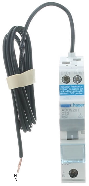
An RCBO is simply an RCD + MCB in one. Popular RCBO models are CLIPSAL C20 RCBM220/30 or HAGER C20 ADC920T. Typical values are 6kV switching voltage, 30mA residual current trigger and 20A overload / short-circuit trigger.
“At what amperage does a 20A breaker trip?”
At anything above 20A if it’s a magnetic-only breaker. Thermal-magnetic breakers follow a thermal overload curve. It may allow a current of 21A for several minutes, 25A for a minute, and 30A for a few seconds, but will open instantly at 40A. It depends on the design of the breaker. You need to look up the specific curve for your device.
“What is the thermal overload curve or trip curve of a breaker?”
Circuit breakers carry a current rating which is the amount of current the breaker can carry continuously. The curve type (B, C, D, etc…) designates the instantaneous trip current range, or the amount of current at which the breaker will trip without any time delay. Generally, the higher the current spike, the faster the breaker will trip. Below you’ll find a list of the the most common curve types and their instantaneous trip ratings.
B Curve: Trips instantaneously above 3 times to 5 times its rated current.
C Curve: Trips instantaneously above 5 times to 10 times its rated current.
D Curve: Trips instantaneously above 10 times to 20 times its rated current.
The HAGER C20 ADC920T is a Thermal(T) RCBO with a curve C, which means it will allow brief current peaks or spikes, like the inrush currents for large motors or the arc start feature for a welder) without tripping. This is part of the overload / short circuit protection (MCB) and not to be confused with the current imbalance or current leakage detection (RCD) that will trip at leak currents as little as 30mA.
Wiring diameter
How many dual general purpose outlets (GPOs) can I have on a single circuit?
It doesn’t work like that. Theoretically you can have a near infinite number of dual GPOs. You need to consider the energy consumption and not overload a circuit. Most circuits have a 20A RCD+MCB, which means you should not have a 2000W oven, a 2000W hotplate, a 1000W microwave and a 1000W water kettle on the same circuit (20A * 240V = 4800W).
What wiring diameter do I need to connect a shed and do some welding?
1.5mm2 = for lights only
2.5mm2 = 4800watts protected by a 20amp circuit breaker
4.0mm2 = 6000watts protected by a (20amp or) 25amp circuit breaker
6.0mm2 = 7680watts protected by a 32amp circuit breaker
10.0mm2 = 9600watts protected by a 40amp circuit breaker
Thermoplastic-Sheathed (TPS) cable
A thermoplastic-sheathed (TPS) cable consists of a toughened outer sheath of polyvinyl chloride (PVC) thermoplastic, covering one or more individual annealed copper conductors, themselves insulated with PVC. This type of wiring is commonly used for residential and light commercial construction in many countries. The flat version of the cable, with two insulated conductors and an uninsulated earth conductor (all within the outer sheath), is referred to as twin and earth. In mainland Europe, a round equivalent is more common.
You can run TPS in ceiling space as long as you keep it away from sharp objects and heat sensitive materials. For metal sheds for added safety you can run in 1 inch (25mm ID) gray PVC electrical conduit. Underground outdoor cabling typically goes in one or more heavy duty (HD) orange 32mm ID electrical conduit and a 600mm deep trench with ‘dig tape’ halfway in between.
TWO PHASES TO SHED OR NOT ?
As far as transmission line is concerned, total current that can be drawn will be of the order of few hundreds of ampere, depending upon diameters of the line conductors and neutral conductor, allowable unbalance current of the distribution transformer etc.
A single phase running over 10mm2 TPS twin core and earth (L + N + Earth) with a 40A breaker will provide more than sufficient current for a hobby / small workshop / liveable shed.
15A GPO
Devices that consume more than 10A (* 240V = 2400 Watts) are typically fitted out with a 15A GPO power plug. These devices can consume up to 15A (*240V = 3600 Watts). Anything bigger would probably require 2 or 3 phase power to spread the power consumption over multiple phases. So what is different about a 15A GPO?
https://www.renovateforum.com/f195/there-any-difference-between-10a-15a-gpo-73298/
It is suggested 15A GPO’s are not all that different from 10A GPOs as far as rocker switch and phase/neutral terminals metal contacts goes [not confirmed].
A 15A GPO has a larger protective earth pin, so all “10A” rated equipment (10A x 240V = 2400W max) is kept separate from any “15A” equipment (15A x 240V = 3600W max). The 15A GPO protective earth pin is just a “key” so you can’t run your 15A equipment on a lower rated circuit (10A) which generally has a lower rated cable.
The difference between 10A and 15A GPO’s is entirely to do with how they are used, not how they are made.
15A outlets always come as single and do not come as double units. You can connect multiple 15A outlets on a single circuit but in most cases electricians prefer to setup a different circuit for each given the high current / power consumption.
As for current carrying capacity the wire diameter is the main factor and the circuit breaker needs to be sized based on the wire diameter. Wire diameter needs to be sized based on expected power consumption of the entire circuit i.e. number of outlets. You would need maybe 50A – 100A to melt a single GPO. The 10A and 15A number is simply an indication of the power rating of the devices plugged in to it.
So with a 15A (averaged; *240V = 3600W) welder and 15A (*240V = 3600W) air compressor you would need at least 6.0mm2 = 7680W protected by a 32amp circuit breaker. If you only use one at a time, you can use 2.5mm2 = 4800watts protected by a 20amp circuit breaker. If you use more, then 10mm2 and 40A breaker.
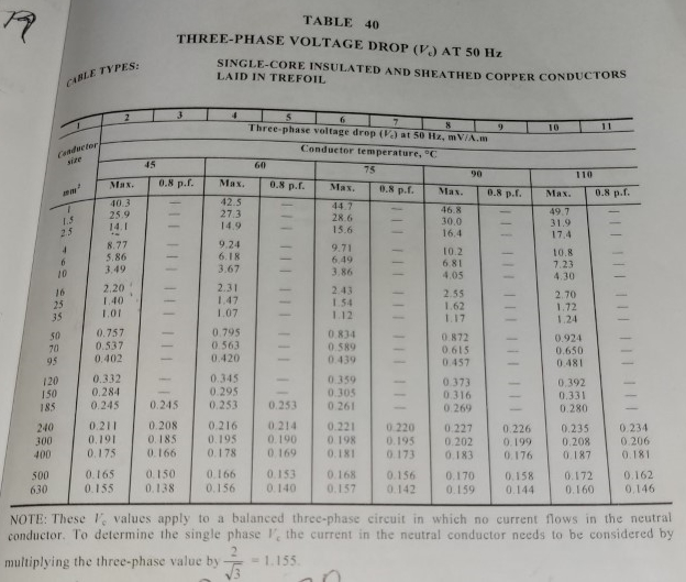
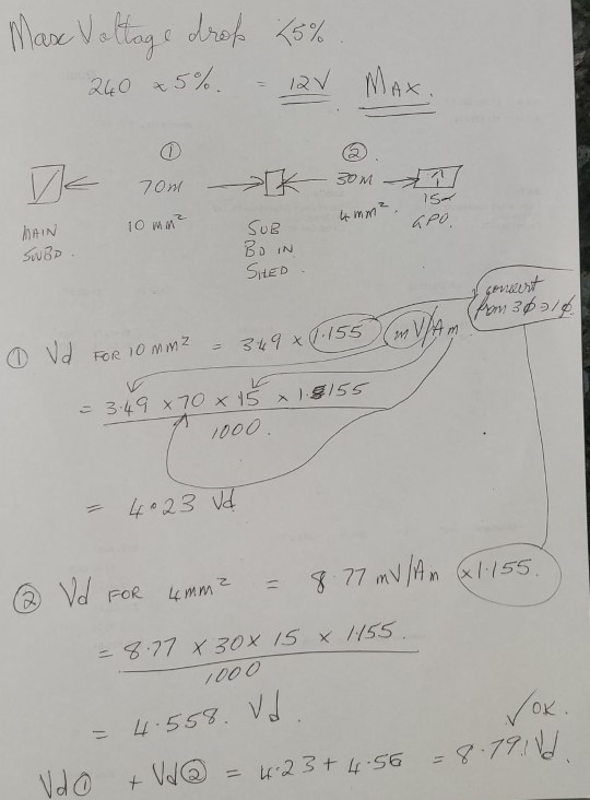
Voltage drop
If you run electricity over long cables, the longer the cable the more the mains voltage of 240Vac will drop. What is the voltage drop if we use 70 meters of 10mm2 from the house to the shed and 30 meters of 4mm2 inside the shed to 15A GPOs ?
Welding
My welder has the following specifications:
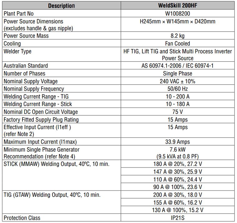
My welder has a Maximum Input Current of 33.9A, an Effective Input Current of 15A and can weld ARC at 180 Amps @ 20% Duty Cycle and TIG at 200 Amps @ 30% Duty Cycle. The welder requires a 15A GPO.
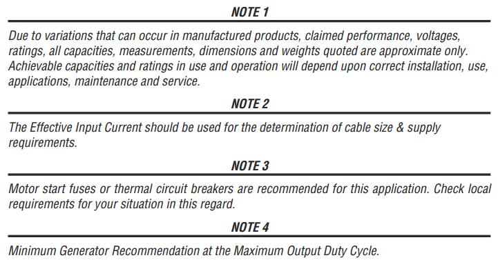
Note where it says “The Effective Input Current should be used for the determination of cable size & supply requirements”
From the manual:
The WeldSkill 200HF is a single phase 15 Amp constant current welding inverter capable of performing 180
Amps in MMAW (Stick) with a maximum electrode size of 4.0mm and 200Amps in GTAW (non-contact start HF Tig and touch start Lift Tig). Simply plug it into any standard 15 Amp power point and get welding right away!
Electric cooktop (‘hotplate’ or ‘stove’, not to be confused with ‘oven’)
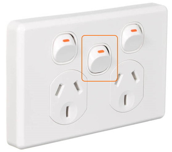
An electric oven consumes between 2000 and 5000 Watts. An electric cooktop consumes between 1500 and 3000 Watts. Electric cooktops (including induction cooktops) require an isolator switch. The isolator must be visible and readily accessible within 2 metres of the appliance and not in a position where the user would have to reach across the cooking surface. Single pole switching is acceptable. If space is limited you can purchase a standard GPO with additional single pole switch.
PVC conduit
Bit of a detour:
Metal tubing from the metal yard comes in square, rectangular and round and is measured as outer diameter (OD) with a certain wall thickness. The square / rectangular tubing is often referred to as Rectangular Hollow Section (RHS). Metal pipe from the metal yard is measured as inner diameter (ID) with a certain wall thickness. Metal comes in painted steel or Zinc galvanized (‘duragal’).
White conduit is telecommunications conduit and isn’t suitable for electrical circuits.
Black poly pipe or polyethylene (PE) pipe with blue stripe indicating drinking water applications is used for pressurised water.
Stormwater pipe is 90mm or 100mm outer diameter. Vertical downpipes are typically 90mm and underground buried horizontal stormwater is 100mm. 100mm is more expensive as it has a higher wall thickness and is significantly stronger.
Finally, electrical conduit is always and only measured outer diameter and comes in two flavours: ‘normal’ UV stabilised gray conduit or ‘heavy duty’ orange conduit. Popular sizes are 20mm, 25mm (1 inch) and 32mm.
I have used 40mm gray electrical pipe across the breezeway ceiling space, 32mm orange HD underground (with 90 degree ‘communications bends’ which have a large radius to make pulling cables easier) and 25mm gray electrical conduit internally.
FINAL SETUP
My welder and air compressor consume 15A each and can run on any 15A GPO (with 2.5mm2 wire on a 20A breaker, 4mm2 wire on a 25A breaker, 6mm2 wire on a 32A breaker or 10mm2 wire on a 40A breaker).
So for now I can run almost everything on 20A breakers with 2.5mm2 wire and pro-actively run a thicker diameter wire than I need to my 15A GPOs. We need to use a smaller 10A RCBO for the lights circuit (Hager ADC310T C10).
Wiring setup:
40A mains single pole circuit breaker MCB in the house meter box.
70 meter long feed-in cable with 3x 10mm2 wires (L + N + Earth) to the shed sub board.
We need an 18 pole sub board in the shed.
We need a 40A mains single pole circuit breaker MCB in the shed sub board.
The two MCBs are there so an electrician can isolate both the 70 meter long feed-in cable and the sub board as desired when servicing.
Shed sub board wiring:
MCB L connects to the RCBO L-IN terminals.
Feed-in cable N connects to a shared neutral terminal block.
Feed-in cable Earth connects to a shared earth terminal block.
Neutral terminal block connects to N-IN black wire of each RCBO.
RCBO L-OUT connects to circuit 3 wire TPS (red).
RCBO N-OUT connects to circuit 3 wire TPS (black).
Earth terminal block connects to circuit 3 wire TPS (yellow/green).
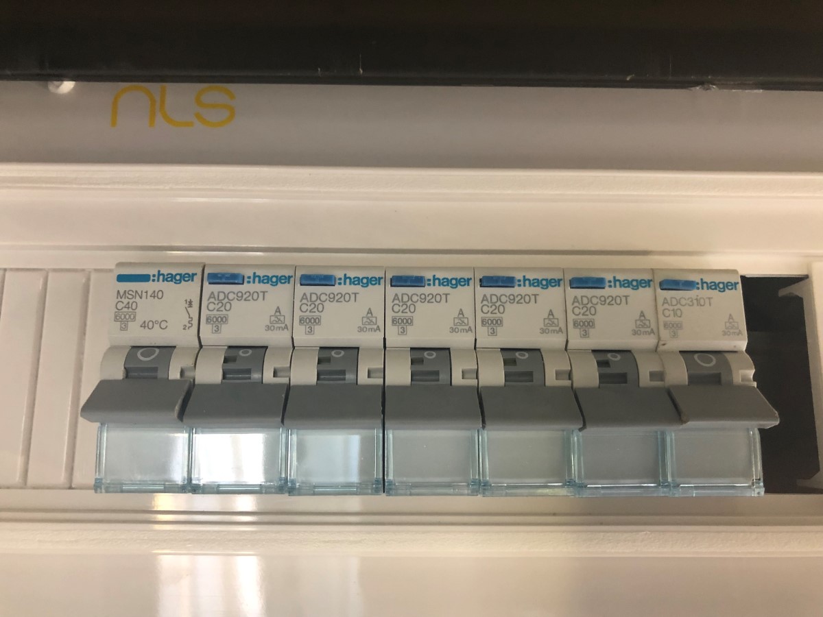
MSN140 C40 40A MCB – Mains single pole breaker.
ADC920T C20 20A RCBO – Liveable bay (microwave, kettle, fridge, TV, room, outdoor, roller door) circuit.
ADC920T C20 20A RCBO – Liveable bay (kitchen hotplate) circuit.
ADC920T C20 20A RCBO – Washer / Dryer circuit.
ADC920T C20 20A RCBO – Workshop bays circuit.
ADC920T C20 20A RCBO – 4mm2 or 10mm2 to two or three 15A GPOs circuit (not to be used simultaneously unless breaker / wiring is matched).
ADC310T C10 20A RCBO (older model) – Lights circuit.
Standard height / depth
Vanity 800mm high
Kitchen bench 900mm high
Bottom of GPO 1000mm high
Light switch
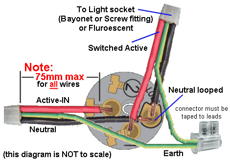
Clipsal rocker switches have a common center terminal with a normal open and normal close terminal adjacent. There is an isolated screw terminal to join wires together, typically neutrals.
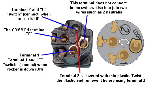
This is how twin-core-and-earth TPS cable is typically wired for a single light point on a single switch.