Ben’s stuff
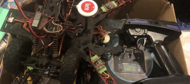
A friend handed me this box of remote control goodies that were sitting on a shelf in need of some attention for me to have some fun with.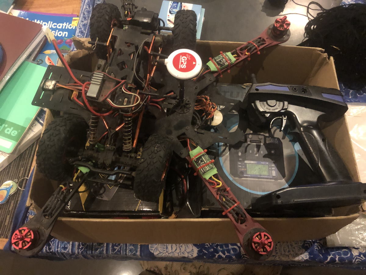
Car
- HSP Racing 1/8th scale electric rock crawler.
- 2S 7.2V NiMH 1800mAh batteries with KET plug.
- Charger is a 9V 250mA DC wall adapter with Tamiya plug to KET plug
- RC540 motor with metal gearbox (1:48.15 ratio)
- 2CH FM servo (steering)
Drone
- Reptile 500 series glass fiber frame.
- Turnigy TGY-i6 transmitter 2.4GHz automatic frequency hopping digital system (AFHDS) version 2A
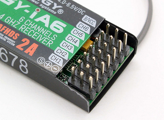
- Turnigy TGY-iA6 receiver
- DJI 2212/920KV brushless motors
- MultiStar v2.0 LBEC2A electronic speed control (ESC)
- Shark X6 Multi-Rotor Flight Control and Autopilot System w/GPS
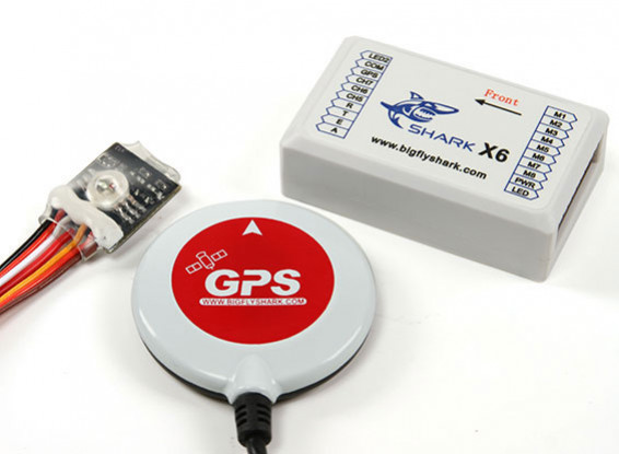
The Shark X6 is the same as the Shark X8. The only difference is plastic housing versus metal housing and built-in SD Card reader.
Turnigy TGY-i6 manual.pdf
shark_x6_8_manual1.pdf
shark_x6_8_manual2.pdf
https://www.rcgroups.com/forums/showthread.php?2288116-Big-Fly-Shark-X6-Flight-Controller/page3
Software
X8 assistant.zip
FlightTools20.zip
FlightTools23.zip
FW_CX20.142.zip
Fw.CX20.148.zip
Fw_CX20_V2_2016-09-05.zip
Pair transmitter and receiver
See Turnigy manual; done. Turn off transmitter. Connect pairing dongle to receiver. Power up receiver. The receiver has a fast blinking red LED. Press and hold pairing button on transmitter. Turn on transmitter. The receiver should slow blink after successful pairing. Remove pairing dongle from receiver. Turn off transmitter. Turn on transmitter. The receiver should have a solid red LED. The receiver is now operational.
Test run
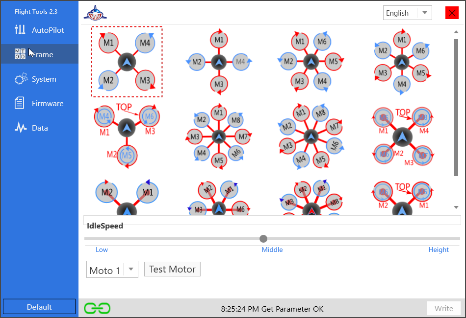
With propellers removed, I was able to get the drone to run all four motors. I had to enable PPM output on the receiver module (RX). This is done by going into setup by holding the OK button on the transmitter (TX) for 2 seconds and changing the setting. To arm the motors the Shark X6 FC wants you to move both sticks into a bottom corner position simultaneously (safety precaution):
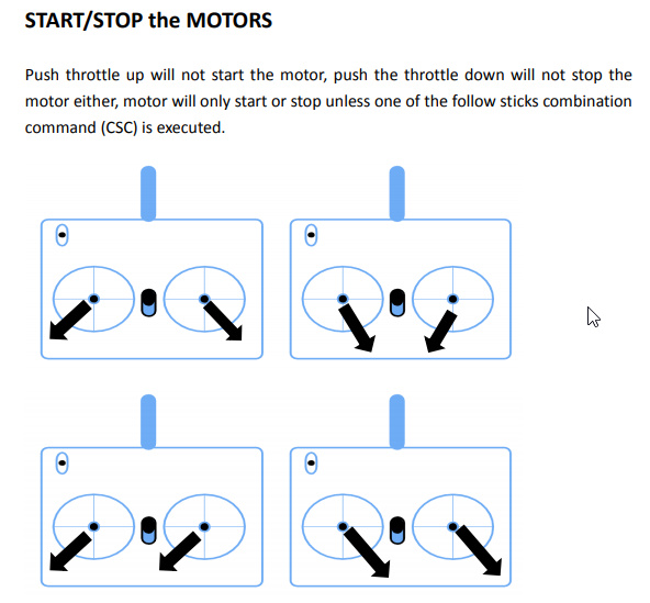
There is 1 green, 2 blue and 2 red LED pulses. I am indoors so the GPS won’t get a lock.
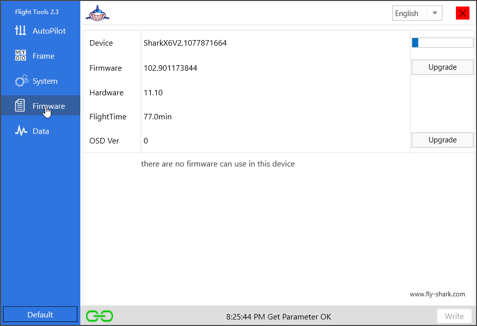
Shark X6 Firmware upgrade
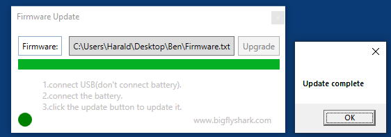
I am able to connect to the Shark X6 flight controller via USB and read / write to the device using a Windows 10 computer. The offline firmware updater utility was also successful. I had to press the “Upgrade” button before connecting the battery to the Shark X6 flight controller for the firmware upgrade to work.
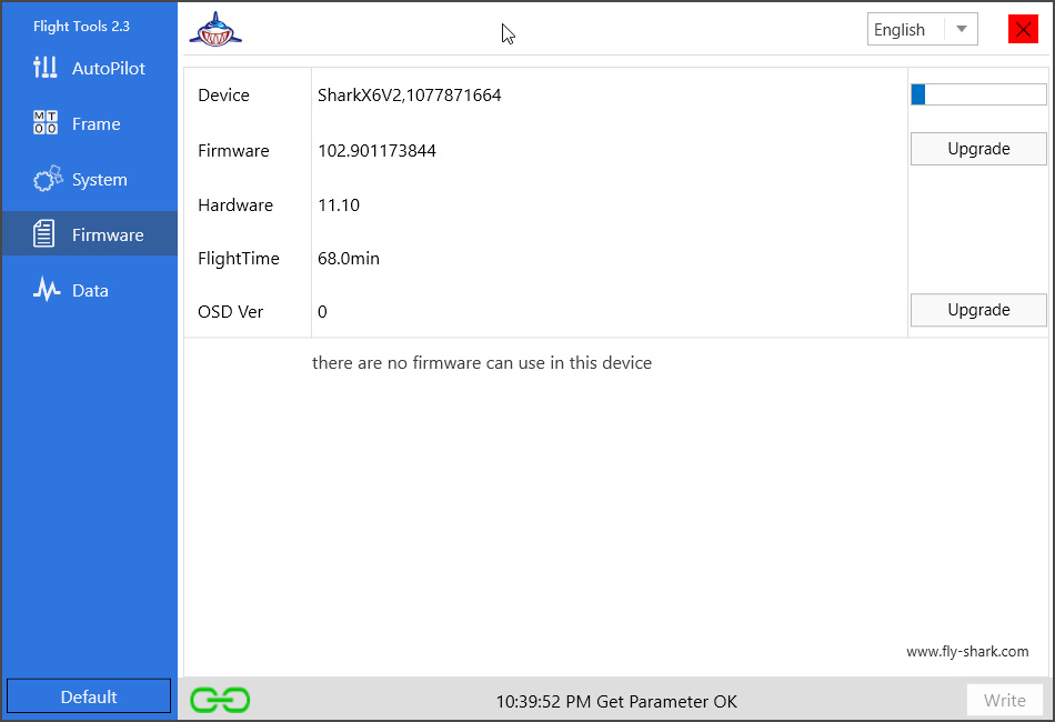
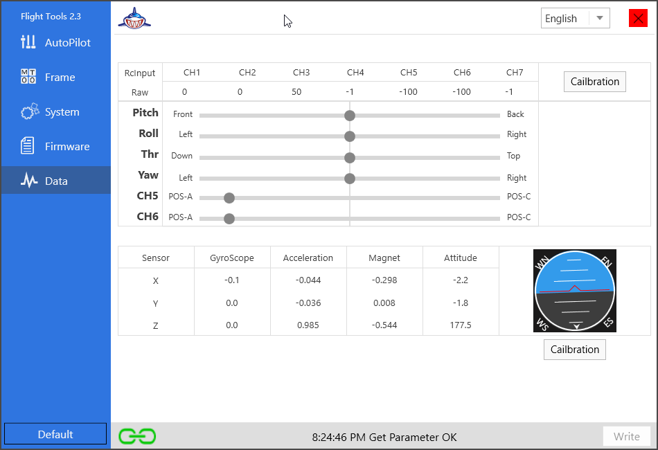
I can now use Flight Tools v23 instead of v20.
[!] Vesion v23 requires that you have the transmitter / receiver active prior to connecting the USB cable. Once I connected the transmitter / receiver and only then connected the USB cable, the status changed from “Waiting For Link” to “Get Parrameter OK”. I was also able to see the response of the accelerometers and gyros and perform an attitude calibration.
Transmitter stick mode and channels
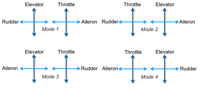
The transmitter is configured as Stick Mode 2: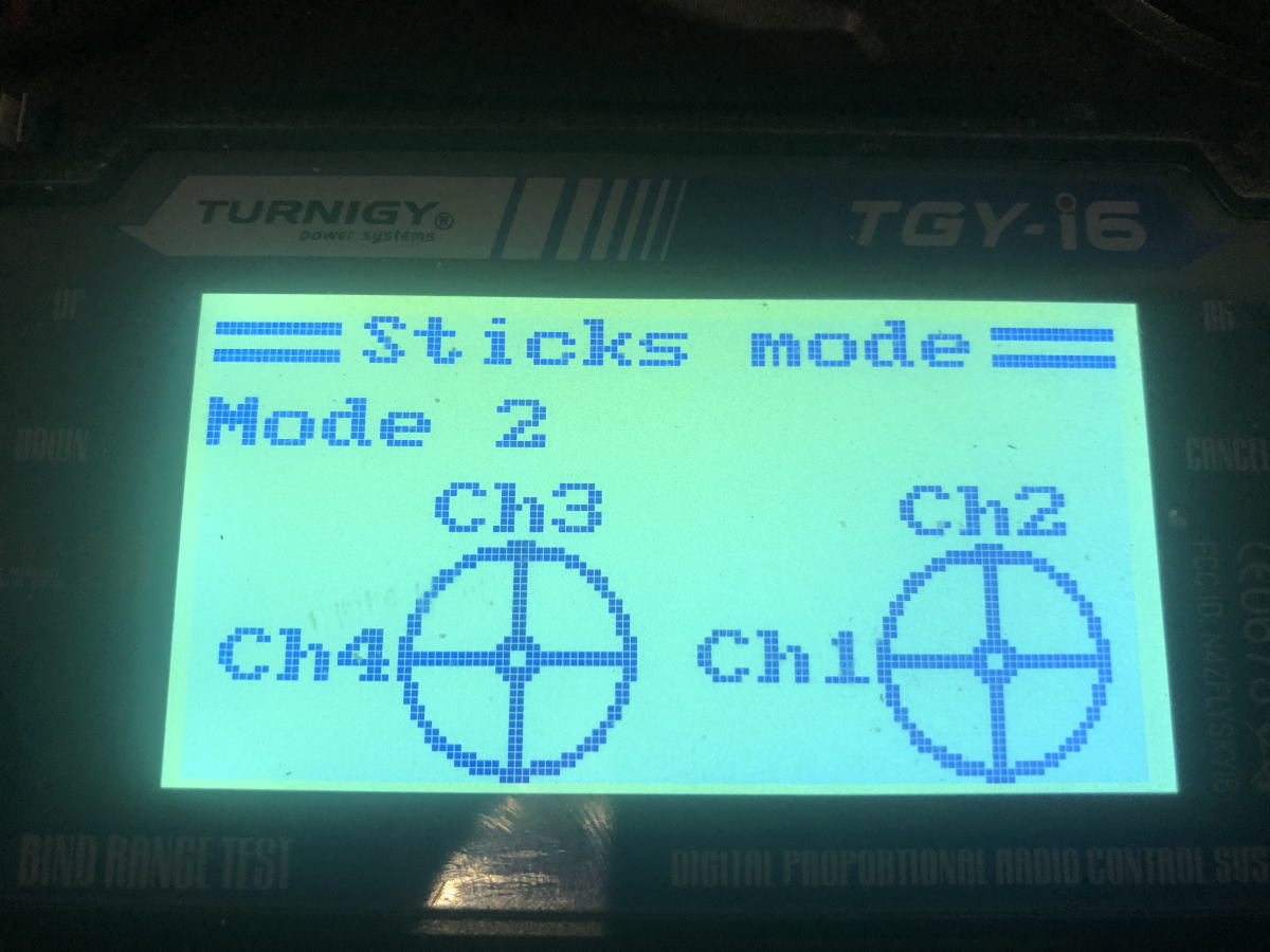
The left hand side stick on the transmitter does not spring back to the neutral center position and is typically used as throttle. So stick mode 2 or mode 4 are suitable for this transmitter. Stick mode 2 is most common.
So we now know which pins on the receiver connect to which pins on the Shark X6 flight controller:
CH1 -> A (aileron)
CH2 -> E (elevator
CH3 -> T (throttle)
CH4 -> R (rudder)
CH5 -> CH5
CH6 -> CH6
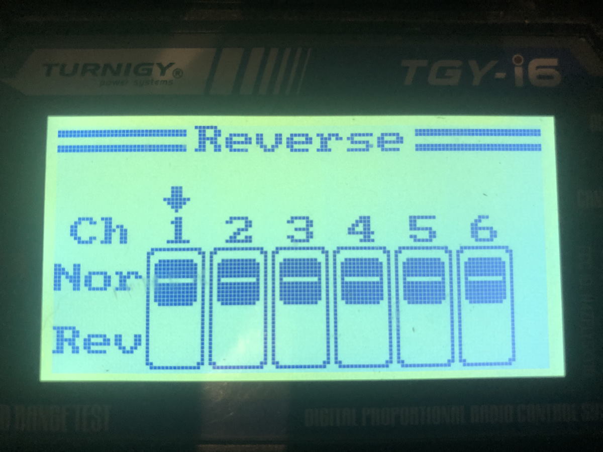
No reverse
Some channels e.g. elevator are typically inverted (‘pull stick towards you to climb’) for airplanes. Drones do not need this. Simply set all channels to normal.
No Subtrim
Make sure stick movement has full range of motion with proper center and is not trimmed in any way.
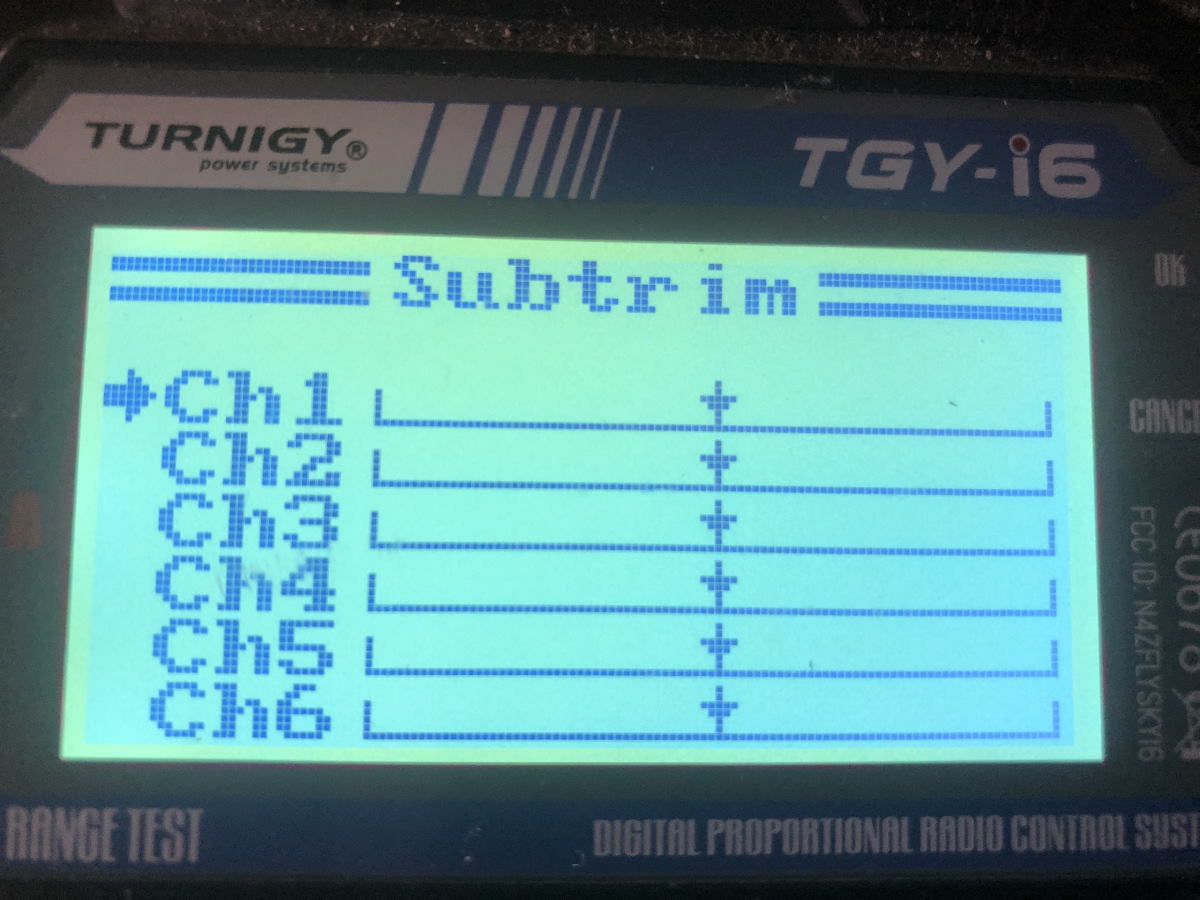
Also make sure endpoints are 100% / 100% for all channels and mixing is disabled.
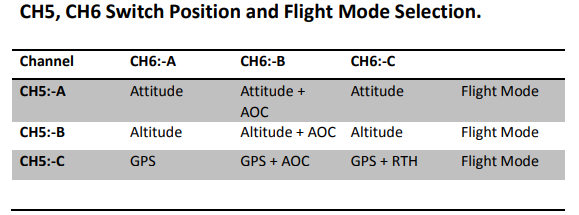
Flight mode switches
CH5 and CH6 need to be mapped to 3 way switches. This transmitter only has a single 3 way switch – Switch C. Switch A, B and D are 2-way switches. I have mapped them as follows for now:
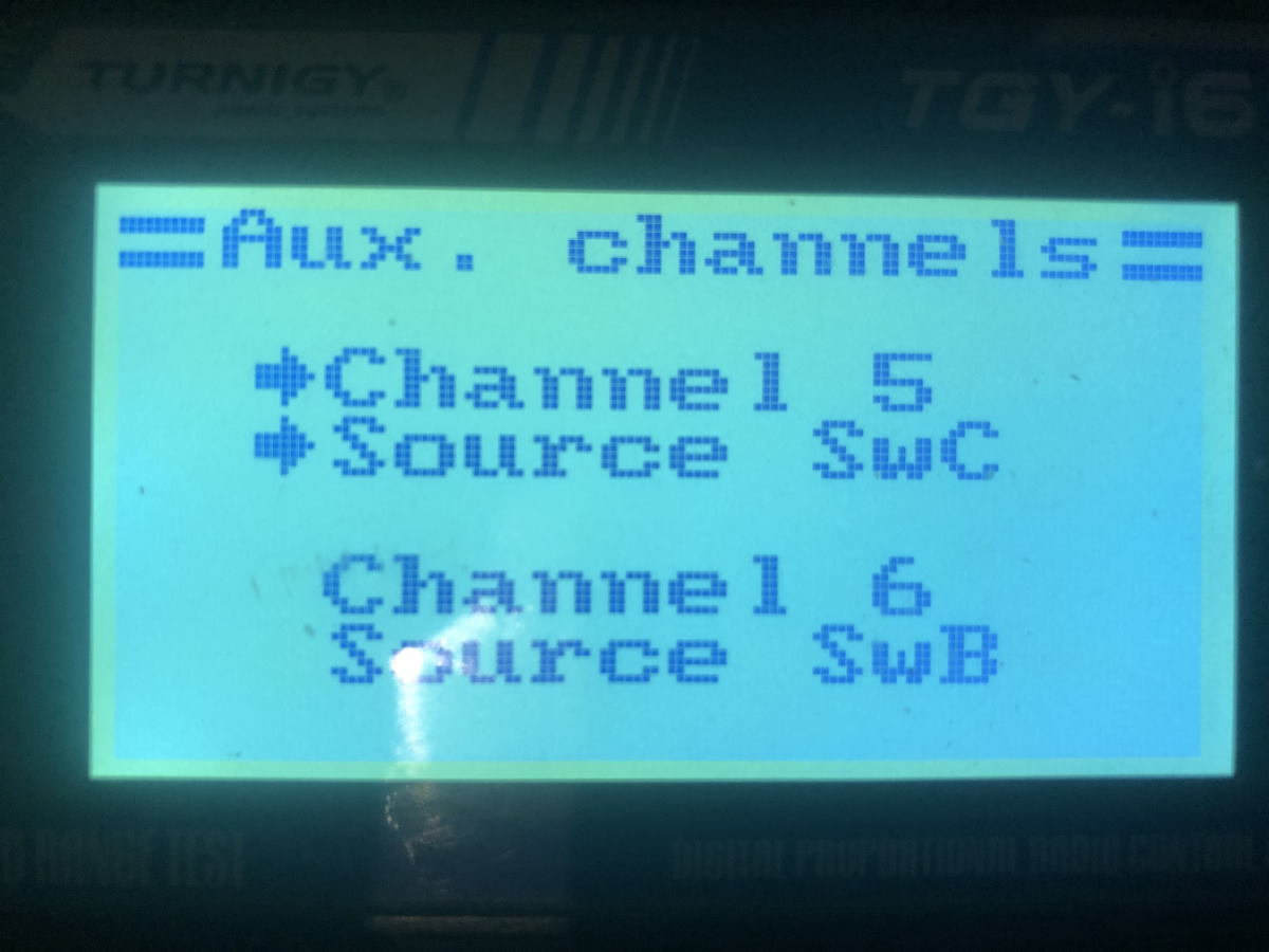
This will allow me to change flight mode. Note the actual switch assignment can be changed in software.
Calibration
Use FlightTools v2.3 to inspect and calibrate the transmitter. Make sure the correct stick operates Throttle, Yaw, Pitch and Roll. Make sure the sticks properly and show full range of motion.
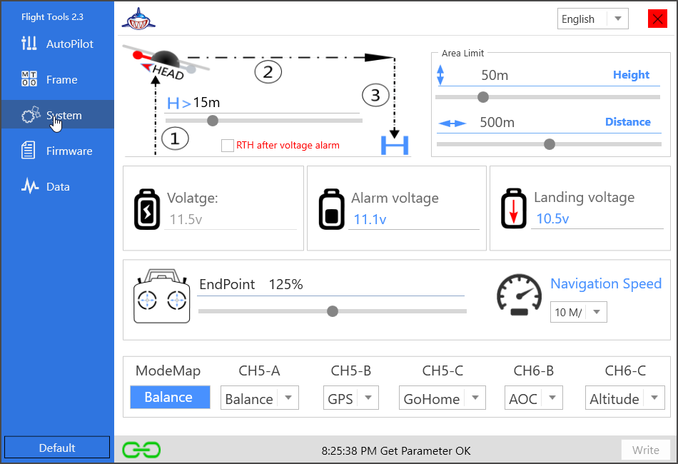
Flight Tools v23 all settings

Maiden Flight I
Low throttle and drone seems to want to tip over. It was suggested to give it more throttle so the flight controller has something it can work with to auto-level.
Maiden Flight II
If I slowly build up throttle all the way to maximum throttle the drone does not get airborne. If however I instantly go maximum throttle the drone leaps off the ground. Will try again soon (it is night time and raining).
Problem #1
The manual mentions the following steps which I am unable to perform:
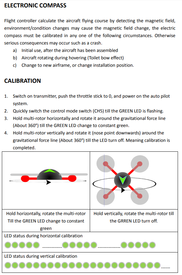
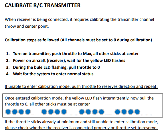
I am certain these steps are the exact same as the Calibration steps in Flight Tools v23. I am confident the transmitter throw and center points are calibrated. The ‘Write’ button remains greyed out, suggesting calibration results are stored immediately. When I attempt to calibrate the compass in Flight Tools v23 nothing much happens. If I disconnect the USB cable however there is a rapid blinking green light as per the manual. The rapid blinking green light does not change as I perform the 360 degrees rotation in horizontal and vertical plane however.
Solution #1
Calibration via Flight Tools v23 works just fine. Compass appears to be calibrated correctly.
Problem #2
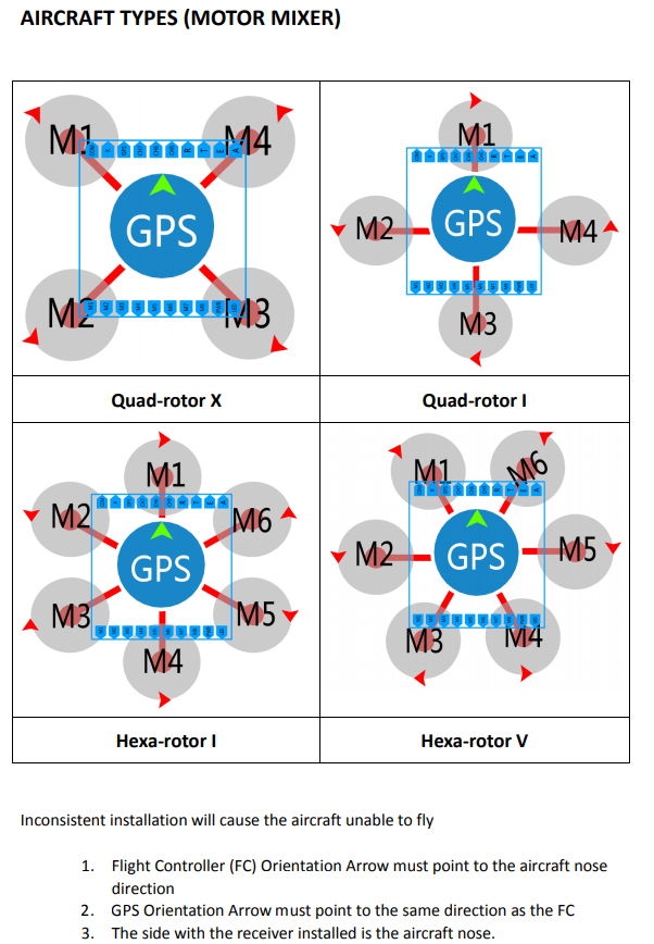
It appears the Shark X6 flight controller is mounted upside down (left-right) in the drone frame, as the top down view in the picture below is different from the actual installation. For example, the LED pin sits over motor M2 in my installation.
Solution #2
The Shark X6 has a different pinout from the Shark X8. The LED pin is in a different location. The correct orientation is where the receiver pins (R, T, E, A) are facing forward towards the receiver and where the Shark X6 sticker labels are facing upward. No change required; flight controller was positioned correctly.
Maiden Flight III
I had to invert channel 2. LiPo battery was end of life. All is well.
Disposing of old LiPo batteries / Battery safety
- Always charge LiPo battery supervised
- Always use the balance charging (balance plug)
- Always use a lipo-safe bag if you have one
- Always dispose LiPo batteries properly.
- NEVER short a LiPo battery.
- NEVER try to use damaged or puffed up LiPo batteries.
- NEVER over-discharge a lipo, it will reduce the life span, and might cause safety issue.
Use a charger with a discharge option to discharge a LiPo battery, or a 12V car halogen bulb (H7). Measure voltage is 0 volt, cut off connector one wire at a time(!) and solder wires together.
2022
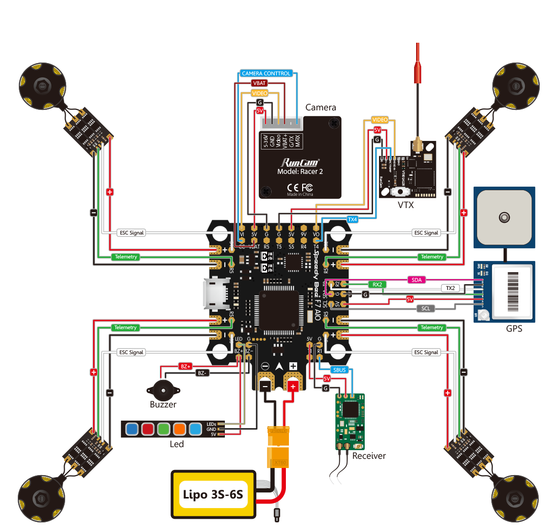
- SpeedyBee F7 AIO flight controller brain transplant. Requires a receiver that can send signals serially over a single pin (!) Has on-board bluetooth for easy configuring of settings using SpeedyBee app. Runs Betaflight firmware out of the box.
- I kept the 4 separate 15A ESCs and mounted them closer to the center of mass. Replacing a single ESC is simpler and cheaper than having to replace a 4-in1 BLHeli_32 ESC that comes as an optional extra for the SpeedyBee F7 AIO. I removed the signal power and signal ground from the ESCs.
- Turnigy TGY-i6 transmitter sends basic PPM stick signals modulated over AFHDS2A carrier. Transmitter also supports digital I-Bus 2-way protocol over AFHDS2A carrier.
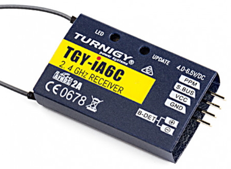
- Replace Turnigy TGY-iA6 receiver with Turnigy TGY-iA6C receiver, which sends all control signals serially using a single signal pin to the flight controller (PPM / S-Bus / I-Bus). S-Bus / I-Bus allows for receiver battery monitoring on transmitter.
Turnigy TGY-iA6C receiver
Channel: 8
Frequency: 2.4GHz ISM Frequency Range
Band width: 500KHz
Band quantity: 135
RF Power: <20dBM
System: AFHDS2A
Code type: GFSK
Output data: PPM, i.BUS, S.BUS
Antenna length: 26mm
Power: 4.0V~6.5V
Wireless Update: Yes
Channel data: Center position: 1500±30us; range: 1000~2000±30us
Channel delay: <15ms
Net Weight: 7.9g
Dimensions: 41x25x10mm
Range: >300 meters
Certification: CE0678, FCC ID: N4ZIA6C00, RCM
SpeedyBee F7 AIO
| MCU | STM32F722 |
| IMU | ICM20689 |
| Baro | BMP280 (I2C) |
| OSD | BetaFlight OSD w/ AT7456E chip |
| BLE Module | inner connect to UART3 for remote setting with SpeedyBee App or other similar apps |
| BlackBox | 32MB onboard dataflash |
| Current Sensor | 200A(Scale 102) |
| BetaFlight Camera Control Pad | Yes |
| Power input | 3s – 6s Lipo |
| Power output | 5V *5(Including BZ+), the maximum load current is 2.5A. 9V * 1, the maximum load current is 2.5A. |
| ESC power output | 4 * VCC output |
| UART | UART Pads * 4(UART1, UART2, UART4, UART5) |
| RSSI input | RSSI input solder pad |
| SmartPort | Use Softserial1 to support SmartPort |
| Support Flight Controller Firmware | Betaflightbeta, iNav(Coming soon) |
| I2C | Used for external Magnetometer, Sonar, etc. |
| Buzzer | BZ+ and BZ- pad used for 5V Buzzer |
| ESC signal | S1 – S5 |
| LED pin | Used for WS2812 LED |
| Boot button | Used to easy enter DFU mode |
| Weight | ≈8.8g |
| Dimension | 36.5 * 44 * 7mm |
Inertial measurement unit IMU chips can contain:
- 3-axis gyroscopic sensor (‘orientation’)
- 3-axis accelerometer sensor (‘inertia’)
- 3-axis magnetometer sensor (‘compass’)
- temperature sensor
Note: Satellite global positioning system (GPS) is external.
The SpeedyBee F7 AIO ICM20689 IMU chip does not have a compass; it does have gyroscopic sensor and accelerometer. This will detect roll, pitch and yaw. The flight controller needs to be mounted facing forward (note arrow symbol silkscreen printed on circuit board). The flight controller can be mounted anywhere but is best placed near the center of mass.
The flight controller uses RX/TX/GND to connect an external GPS and I2C protocol (SCL / SDA / GND) to connect a earth magnetic field compass. A combined GPS / compass modules Beitian-180 or Matek M8Q-5883 are popular and suitable candidates. This may be added later for waypoint navigation.