MPCNC part 1
I plan to build a desktop CNC machine capable of milling aluminium.
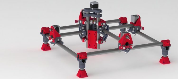
The “Mostly Printed CNC” (MPCNC) machine is what I will be building.
https://www.v1engineering.com/specifications/
https://www.v1engineering.com/assembly/
https://www.v1engineering.com/forum/topic/mpcnc-with-double-belt-setup/
This will be a long term project and a bit of a journey.
Step 1. Learn how to 3D print
For long I considered 3D printers somewhat of a toy. 3D printers together with M3 M4 M5 bolts and nuts, 608-2RS skateboard wheel bearings and Thingiverse / Fusion 360 open up a world of possibilities for manufacturing and rapid prototyping. I will need to learn how to 3D print. I purchased an inexpensive 3D printer with the following features:
- Relatively inexpensive ($280 AUD).
- 24Vdc 15A power supply (350W).
- Arduino based control board with bootloader.
- Glass bed.
- Print from SD card.
- Resume print (filament detection).
- 3Dtouch ready. 3D touch allows for auto Z height and automatic bed leveling.
- Trinamic stepper motor driver ready (TMC2208) for quiet operation.
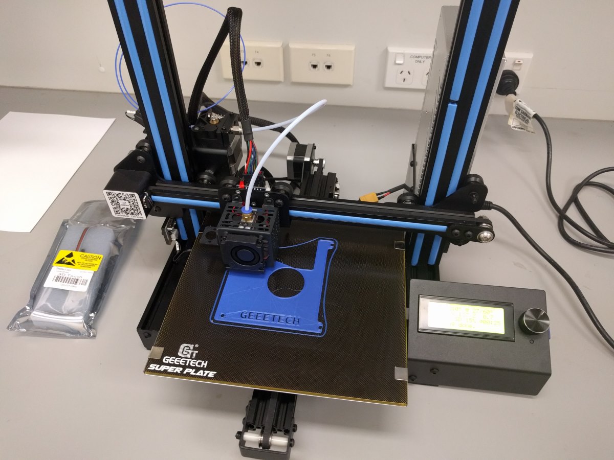
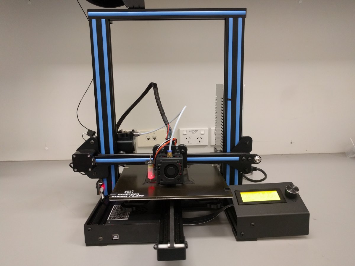

Metal clips on hotbed
Metal clips clamp the glass plate and the aluminium hotbed together. Metal clips are not glued and can be easily removed. When removing the clips be careful not to scratch the insulation of the hotbed exposing the copper traces(!) I noticed the metal clips on the bed were actually mounted sort of upside down. It is best to mount the clips as follows in my view:
- Metal clips should be attached with the flat side facing up. Benefits:
- nozzle doesn’t bump into clips.
- smaller contact area underneath hotbed prevents scratches / shorts.
- Metal clips should be attached on the left and right hand side of the hotbed; not on the front or rear as it can create shorts more easily.
- Put some heatshrink tubing on the curved bit of each metal clip where the clip touches the underside of the hotbed. Heatshrink tubing starts shrinking at 100+ degrees Celcius and will withstand 60 degrees Celcius.
- When attaching the metal clips slide them on at an angle. Try to place the clip in position on the bottom of the hotbed first and then angle the metal clip upwards to snap it over the glass plate.
Bed adhesion
Without a heated hotbed the corners of your prints will warp and lift when the plastic filament cools down and shrinks. For simple and inexpensive bed adhesion printing PLA on a glass hotbed use the following method:
- Clean glass plate with paper towel, cold water and dish soap.
- In a small cup, mix a small amount of half and half volume sugar and water.
- Apply the water / sugar mix onto the glass plate with a paper towel.
3dtouch
http://www.geeetech.com/wiki/index.php/3DTouch_Auto_Leveling_Sensor
- Download Arduino 1.8.5
- Download Geeetech firmware as a *.ZIP file
- Extract firmware folder for your model 3D printer + 3dtouch.
- Find and open Marlin.ino in Arduino software.
- Connect 3D printer and turn on.
- Install FTDI or CH43 USB driver on your computer if need be.
- In Arduino software suite, set board to Arduino MEGA 2560.
- Set port to (see Device Manager on your computer).
- Compile and Upload code.
- Setup your 3Dtouch as shown in the video.
- Add a new instruction G29 after the existing instruction G28 to your ‘Start G-code’ settings in your slicer software. This will run a bed leveling routine after autohoming (X by endstop, Y by endstop and Z by 3Dstouch).
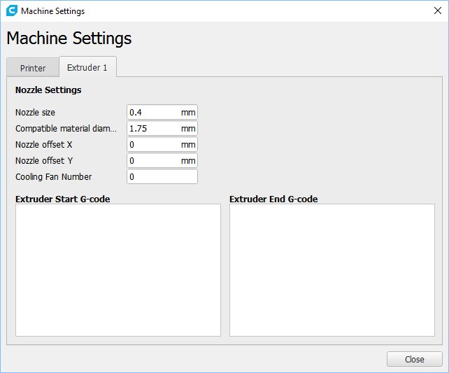
Cura printer profile for Geeetech A10 printer
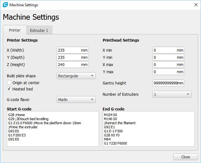
Update: Changed “G1 E-1 F300” to “G1 E-30 F300” to retract the filament 3cm instead of 1mm. This allows me to easily remove the filament after printing for storing without having to heat the nozzle to 180+ degrees Celsius. I also moved the “G28 X0 Y0” homing instruction up so it will return to the origin before performing the slow retract operation. Without this, the hot nozzle will leave an imprint on the object printed.
Cura print settings profile
Click here to download my Cura print settings profile (*.ZIP file)
Update: Search for “initial” and change initial layer height from 0.15mm to 0.30mm
Step 2. Determine the size of your MPCNC machine
https://www.v1engineering.com/assembly/machine-size/
https://www.v1engineering.com/assembly/conduit-rails-tubes-pipes/
Milling or Routing…Everything But 3D Printing
“This geometry is best with short legs and a short z axis. It was designed first and foremost as a cnc mill/router. If you think about it on those terms standard bits are no longer than 1″-1.5″ so you actually only need that much travel in the z axis, any more is just for material clearance and there are other ways to deal with that, like a drop table. Keeping a short z axis and short legs keeps the machine as rigid, accurate, and as fast as possible. This is the same for laser, drag knife, foam cutting, plotting, ect.”
” I recommend starting with a foot print of 24″ X 24″ (600 x 600mm) Outer Dimensions with a 3-4″ (75mm – 100mm) usable height.”
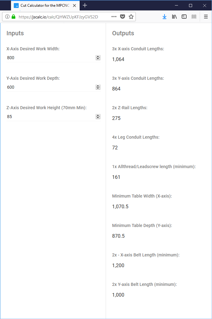
My goal is to be able to mill up to 10mm thick aluminium sheet metal, but also 1″+ (25mm+) wood / foam using up to 1″ (25mm) tall cutting bits. 800mm x 600mm x 85mm (X * Y * Z) seems like a good compromise for a desktop CNC router. I want to keep the sides open to be able to slide in larger work pieces i.e. engraving long narrow timber signs letter by letter.
I am using the metric calculator:
https://jscalc.io/calc/QHWZUpKFJzyGVS2D
In a next episode we will start 3D printing and cutting round tube.